What brand of pipe is used on the steam pipeline. What thickness to choose a steel pipe. Selection of pipes for communications
Abstract on the topic:
Steam line
Steam line- pipeline for steam transportation. It is used in enterprises that use steam as a technological product or energy carrier, for example, in thermal or nuclear power plants, in reinforced concrete factories, in the food industry, in steam heating systems, and many others. etc. Steam lines are used to transfer steam from the place of receipt or distribution to the place of steam consumption (for example, from steam boilers to turbines, from turbine outlets to technological consumers, to the heating system, etc.) The steam line from the steam boiler to the turbine at power plants is called the "main" steam line, or the "hot" steam line.
The main elements of a steam pipeline are steel pipes, connecting elements (flanges, bends, elbows, tees), shut-off and shut-off and control valves (gates, valves), drainage devices, thermal expansion compensators, supports, hangers and fastenings, thermal insulation.
The routing is carried out taking into account the minimization of energy losses due to the aerodynamic resistance of the steam path. The connection of steam pipeline elements is made by welding. Flanges are allowed only for connecting steam pipelines to fittings and equipment.
To avoid energy losses, a minimum of shut-off and control valves are installed on steam pipelines. Stop and control valves are installed on the main steam pipelines of power plants, which are the main means of switching on and regulating turbine power.
According to the strength conditions, the wall thickness of the steam pipeline must be no less than: where
P- design steam pressure, D- outer diameter of the steam line, φ - design strength factor taking into account welds and section weakening, σ - permissible stress in the metal of the steam pipeline at the design steam temperature.The supports and hangers of steam pipelines are designed to be movable or fixed. Lyre-shaped or U-shaped compensators are installed between adjacent fixed supports in a straight section, which reduce the effects of deformation of the steam pipeline under the influence of heating (1 m of steam pipeline lengthens by an average of 1.2 mm when heated by 100°) [ source not specified 458 days] .
To reduce the ingress of condensate drops into steam engines (especially turbines), steam lines are installed with a slope and equipped with the so-called. “condensation traps”, which trap condensate formed in the pipes, and also install various separation devices in the steam path.
Horizontal sections of the pipeline must have a slope of at least 0.004 [ source not specified 458 days] .
All pipeline elements with an outer wall surface temperature above 55 °C [ source not specified 458 days], located in places accessible to operating personnel, must be covered with thermal insulation. Thermal insulation also reduces heat loss into the atmosphere. Since at high temperatures steel exhibits creep (creep) [ source not specified 458 days], to control deformations of the steam lines, bosses are welded to the surface. These places must have removable insulation. The insulation of steam lines is usually covered with tin or aluminum casings.
Steam pipelines are a hazardous production facility and must be registered with specialized registration and supervisory authorities (in Russia - the territorial department of Rostechnadzor). Permission to operate newly installed steam pipelines is issued after their registration and technical examination. During operation, technical examination and hydraulic tests of steam pipelines are periodically carried out.
Literature
- PB 10-573-03 Rules for the design and safety of operation of steam and hot water pipelines. Approved by Resolution of the State Mining and Technical Supervision of the Russian Federation dated June 11, 2003 No. 90.
- NP-045-03 Rules for the design and safe operation of steam and hot water pipelines for nuclear energy facilities. Approved by resolutions of Gosatomnadzor No. 3, Gosgortekhnadzor No. 100 dated June 19, 2003.
- A manual for calculating the strength of technological steel pipelines at Py up to 10 MPa. M.: TsITP, 1989.
Steam line- pipeline for steam transportation.
Steam pipelines are installed at the following sites:
1. enterprises using steam for process steam supply (steam-condensate systems at factories of reinforced concrete products, steam-condensate systems at fish processing plants, steam-condensate systems at dairies, steam-condensate systems at meat processing plants, steam-condensate systems at factories in the pharmaceutical industry, steam-condensate systems in cosmetics factories, steam-condensate systems in laundry factories)
2. in steam heating systems of factories and industrial enterprises. It was used in the past but is still used in many enterprises. As a rule, factory boiler houses were built according to standard drawings using DKVR boilers for process steam supply and heating. Currently, even in those enterprises and factories where the need for process steam has become absent, heating is still carried out with steam. In some cases, it is ineffective without condensate return.
3. in thermal power plants to supply steam to steam turbines to generate electricity.
Steam lines serve to transfer steam from the boiler room (steam boilers and steam generators) to steam consumers.
The main elements of the steam pipeline are:
1.steel pipes
2. connecting elements (bends, elbows, flanges, thermal expansion compensators)
3. shut-off and shut-off and control valves (gate valves, valves, valves)
4. fittings for removing condensate from steam pipelines - condensate traps, separators,
5. Devices for reducing steam pressure to the required value - pressure regulators
6. Mechanical dirt filters with replaceable filter elements for cleaning steam in front of pressure reducing valves.
7. fastening elements - sliding supports and fixed supports, suspensions and fastenings,
8. thermal insulation of steam pipelines - temperature-resistant basalt mineral wool Rockwool or Parok is used, asbestos fluff cord is also used.
9.control and measuring instruments (instrumentation) - pressure gauges and thermometers.
Requirements for the design, construction, materials, manufacture, installation, repair and operation of steam pipelines are regulated by regulatory documents.
-Pipelines transporting water steam with a working pressure of more than 0.07 MPa (0.7 kgf/cm2) are subject to the “Rules for the construction and safe operation of steam and hot water pipelines” (PB 10-573-03).
-The strength calculations of such steam pipelines are carried out in accordance with the “Standards for strength calculations of stationary boilers and steam and hot water pipelines” (RD 10-249-98).
The routing of steam pipelines is carried out taking into account the technical feasibility of laying along the shortest route to minimize heat and energy losses due to the length of the laying and the aerodynamic resistance of the steam path.
The connection of steam pipeline elements is made by welding joints. Installation of flanges when installing steam pipelines is allowed only for connecting steam pipelines to fittings.
Supports and hangers of steam pipelines can be movable or fixed. Lyre-shaped or U-shaped compensators are installed between adjacent fixed supports on a straight section, which reduce the effects of deformation of the steam pipeline under the influence of heating (1 m of steam pipeline lengthens by an average of 1.2 mm when heated by 100°).
Steam pipelines are installed with a slope and condensate traps are installed at the lowest points to remove condensate formed in the pipes. Horizontal sections of the steam pipeline must have a slope of at least 0.004. At the entrance of steam pipelines to workshops, at the exit of steam pipelines from boiler rooms, in front of steam-consuming equipment, steam separators are installed complete with condensate traps.
All elements of steam pipelines must be covered with thermal insulation. Thermal insulation protects personnel from burns. Thermal insulation prevents excessive condensation.
Steam pipelines are a hazardous production facility and must be registered with specialized registration and supervisory authorities (in Russia - the territorial department of Rostechnadzor). Permission to operate newly installed steam pipelines is issued after their registration and technical examination.
The wall thickness of the steam pipeline, according to strength conditions, must be no less than where
P - design steam pressure,
D is the outer diameter of the steam line,
φ - design strength coefficient taking into account welds and section weakening,
σ is the permissible stress in the metal of the steam pipeline at the design steam temperature.
The diameter of the steam pipeline is usually determined based on the maximum hourly steam flow and the permissible pressure and temperature losses using the velocity method or the pressure drop method. Speed method.
Having specified the rate of steam flow in the pipeline, its internal diameter is determined from the mass flow equation, for example, by the expression:
D= 1000 √ , mm
Where G is the mass flow rate of steam, t/hour;
W-steam speed, m/s;
ρ - steam density, kg/m3.
The choice of steam velocity in steam lines is important.
According to SNiP 2-35-76, steam speeds are recommended no more than:
- for saturated steam 30 m/s (for pipe diameters up to 200 mm) and 60 m/s (for pipe diameters over 200 mm),
- for superheated steam 40 m/s (for pipe diameters up to 200 mm) and 70 m/s (for pipe diameters over 200 mm).
Factories producing steam equipment recommend that when choosing the diameter of a steam pipeline, the steam speed should be within the range of 15-40 m/s. Suppliers of mixed steam/water heat exchangers recommend a maximum steam velocity of 50 m/s.
There is also a pressure drop method based on the calculation of pressure losses caused by the hydraulic resistance of the steam pipeline. To optimize the choice of steam line diameter, it is also advisable to evaluate the drop in steam temperature in the steam line, taking into account the thermal insulation used. In this case, it becomes possible to choose the optimal diameter in relation to the drop in steam pressure to the decrease in its temperature per unit length of the steam line (there is an opinion that it is optimal if dP/dT = 0.8...1.2).
The correct choice of a steam boiler and the steam pressure it provides, the choice of configuration and diameters of steam pipelines, steam equipment by class and manufacturer, these are the components of good operation of the steam-condensate system in the future.
And many more. etc. Steam lines are used to transfer steam from the place of receipt or distribution to the place of steam consumption (for example, from steam boilers to turbines, from turbine outlets to technological consumers, to the heating system, etc.) The steam line from the steam boiler to the turbine at power plants is called the "main" steam line, or the "hot" steam line.
The main elements of a steam pipeline are steel pipes, connecting elements (flanges, bends, elbows, tees), shut-off and shut-off and control valves (gates, valves), drainage devices, thermal expansion compensators, supports, hangers and fastenings, thermal insulation.
The routing is carried out taking into account the minimization of energy losses due to the aerodynamic resistance of the steam path. The connection of steam pipeline elements is made by welding. Flanges are allowed only for connecting steam pipelines to fittings and equipment.
To avoid energy losses, a minimum of shut-off and control valves are installed on steam pipelines. Stop and control valves are installed on the main steam pipelines of power plants, which are the main means of switching on and regulating turbine power.
According to the strength conditions, the wall thickness of the steam pipeline must be no less than: where
P- design steam pressure, D- outer diameter of the steam line, φ - design strength coefficient taking into account welds and section weakening, σ - permissible stress in the metal of the steam pipeline at the design steam temperature.The supports and hangers of steam pipelines are designed to be movable or fixed. Lyre-shaped or U-shaped compensators are installed between adjacent fixed supports on a straight section, which reduce the effects of deformation of the steam pipeline under the influence of heating (1 steam pipeline lengthens by an average of 1.2 mm when heated by 100).
To reduce the ingress of condensate drops into steam engines (especially turbines), steam lines are installed with a slope and equipped with the so-called. “condensation traps”, which trap condensate formed in the pipes, and also install various separation devices in the steam path.
Horizontal sections of the pipeline must have a slope of at least 0.004.
All pipeline elements with an outer wall surface temperature above 55 °C, located in places accessible to operating personnel, must be covered with thermal insulation. Thermal insulation also reduces heat loss into the atmosphere. Since steel exhibits creep at high temperatures, bosses are welded to the surface to control deformation of steam lines. These places must have removable insulation. The insulation of steam lines is usually covered with tin or aluminum casings.
Steam pipelines are a hazardous production facility and must be registered with specialized registration and supervisory authorities (in Russia - the territorial department of Rostechnadzor). Permission to operate newly installed steam pipelines is issued after their registration and technical examination. During operation, technical examination and hydraulic tests of steam pipelines are periodically carried out.
Literature
- PB 10-573-03 Rules for the design and safety of operation of steam and hot water pipelines. Approved by Resolution of the State Mining and Technical Supervision of the Russian Federation dated June 11, 2003 No. 90.
- NP-045-03 Rules for the design and safe operation of steam and hot water pipelines for nuclear energy facilities. Approved by resolutions of Gosatomnadzor No. 3, Gosgortekhnadzor No. 100 dated June 19, 2003.
- A manual for calculating the strength of technological steel pipelines at Py up to 10 MPa. M.: TsITP, 1989.
Wikimedia Foundation. 2010.
Synonyms:See what “Steam pipeline” is in other dictionaries:
Steam line... Spelling dictionary-reference book
steam line- (steam line is not recommended) ... Dictionary of difficulties of pronunciation and stress in modern Russian language
STEAM PIPELINE, steam pipeline, male (those.). A pipeline through which steam passes. Ushakov's explanatory dictionary. D.N. Ushakov. 1935 1940 ... Ushakov's Explanatory Dictionary
- (Steam conduit) a pipeline that conducts steam to machines and auxiliary mechanisms. Samoilov K.I. Marine dictionary. M. L.: State Naval Publishing House of the NKVMF of the USSR, 1941 ... Marine Dictionary
Noun, number of synonyms: 5 air duct (5) gas-air duct (6) ... Synonym dictionary
steam line- Pipeline with shut-off and control equipment for transporting steam [Terminological dictionary for construction in 12 languages (VNIIIS Gosstroy USSR)] Topics of heat power engineering in general EN steam conduitsteam line DE Dampfumformer FR conduite ... Technical Translator's Guide
Steam line- – pipeline with shut-off and control equipment for transporting steam. [Terminological dictionary of construction in 12 languages (VNIIIS Gosstroy USSR)] Term heading: Thermal equipment Encyclopedia headings: Abrasive... ... Encyclopedia of terms, definitions and explanations of building materials
Pipeline with shut-off and control equipment for transporting steam (Bulgarian language; Български) steam pipeline (Czech language; Čeština) parovod (German language; Deutsch) Dampfumformer (Hungarian language; Magyar) gőzvezeték (Mongolian language)… … Construction dictionary
steam line- garo vamzdis statusas T sritis automatika atitikmenys: engl. steam pipe vok. Dampfleitung, f rus. steam line, m pranc. tuyau à vapeur, m … Automatikos terminų žodynas
steam line- garotiekis statusas T sritis Energetika apibrėžtis Vamzdynas garui transportuoti. Garotiekis paprastai montuojamas iš plieninių trauktinių vamzdžių. Mažo slėgio (iki 1.2 MPa) garotiekis gali būti jungiamas jungėmis, vidutinio ir didelio slėgio –… … Aiškinamasis šiluminės ir branduolinės technikos terminų žodynas
METHODOLOGY
calculating the strength of the main pipeline wall according to SNiP 2.05.06-85*
(compiled by Ivlev D.V.)
Calculating the strength (thickness) of the main pipeline wall is simple, but when doing it, a number of questions arise for the first time about where and what values are taken from the formulas. This strength calculation is carried out under the condition that only one load is applied to the pipeline wall - the internal pressure of the transported product. When taking into account the influence of other loads, a verification calculation for stability must be carried out, which is not considered in this methodology.
The nominal thickness of the pipeline wall is determined by formula (12) SNiP 2.05.06-85*:
n - reliability factor for load - internal operating pressure in the pipeline, taken according to Table 13* SNiP 2.05.06-85*:
| Nature of load and impact | Pipeline laying method | Load safety factor | ||
| underground, above ground (in an embankment) | aboveground | |||
| Temporary long-term | Internal pressure for gas pipelines | + | + | 1,10 |
| Internal pressure for oil pipelines and oil product pipelines with a diameter of 700-1200 mm with intermediate pressure points without connecting containers | + | + | 1,15 | |
| Internal pressure for oil pipelines with a diameter of 700-1200 mm without intermediate or with intermediate oil pumping stations operating constantly only with a connected container, as well as for oil pipelines and oil product pipelines with a diameter of less than 700 mm | + | + | 1,10 |
p - working pressure in the pipeline, in MPa;
D n - outer diameter of the pipeline, in millimeters;
R 1 - design tensile strength, in N/mm 2. Determined by formula (4) SNiP 2.05.06-85*:

Temporary tensile strength on transverse samples, numerically equal to the tensile strength σ in the pipeline metal, in N/mm 2. This value is determined by steel regulations. Very often, only the strength class of the metal is indicated in the source data. This number is approximately equal to the tensile strength of steel, converted to megapascals (example: 412/9.81=42). The strength class of a specific steel grade is determined by analysis in the factory only for a specific melt (ladle) and is indicated in the steel certificate. The strength class may vary within small limits from batch to batch (for example, for steel 09G2S - K52 or K54). For reference, you can use the following table:
m is the coefficient of pipeline operating conditions depending on the category of the pipeline section, adopted according to Table 1 of SNiP 2.05.06-85*:
The category of the main pipeline section is determined during design according to Table 3* of SNiP 2.05.06-85*. When calculating pipes used under conditions of intense vibration, the coefficient m can be taken equal to 0.5.
k 1 - reliability coefficient for the material, taken according to Table 9 of SNiP 2.05.06-85*:
| Pipe characteristics | The value of the reliability coefficient for the material is to 1 |
| 1. Welded from low-pearlite and bainitic steel of controlled rolling and thermally strengthened pipes, manufactured by double-sided submerged arc welding along a continuous technological seam, with a minus tolerance for wall thickness of no more than 5% and passed 100% control for the continuity of the base metal and welded joints non-destructive methods | 1,34 |
| 2. Welded from normalized, thermally strengthened steel and controlled rolling steel, manufactured by double-sided submerged arc welding along a continuous technological seam and having passed 100% control of welded joints using non-destructive methods. Seamless from rolled or forged billets, 100% tested by non-destructive methods | 1,40 |
| 3. Welded from normalized and hot-rolled low-alloy steel, manufactured by double-sided electric arc welding and passed 100% control of welded joints using non-destructive methods | 1,47 |
| 4. Welded from hot-rolled low-alloy or carbon steel, manufactured by double-sided electric arc welding or high-frequency currents. Other seamless pipes | 1,55 |
| Note. It is allowed to use odds of 1.34 instead of 1.40; 1.4 instead of 1.47 and 1.47 instead of 1.55 for pipes made by double-layer submerged arc welding or electric welding with high frequency currents with walls no more than 12 mm thick using a special production technology that allows obtaining pipe quality corresponding to this coefficient 1 |
Approximately, the coefficient for K42 steel can be taken as 1.55, and for K60 steel as 1.34.
k n - reliability coefficient for the purpose of the pipeline, adopted according to Table 11 SNiP 2.05.06-85*:
It may be necessary to add an allowance for corrosion damage to the wall during the operation of the pipeline to the value of the wall thickness obtained by formula (12) SNiP 2.05.06-85*.
The estimated service life of the main pipeline is indicated in the project and is usually 25-30 years.
To take into account external corrosion damage along the main pipeline route, an engineering-geological survey of soils is carried out. To take into account internal corrosion damage, the pumped medium is analyzed and the presence of aggressive components in it.
For example, natural gas prepared for pumping belongs to a slightly aggressive environment. But the presence of hydrogen sulfide and (or) carbon dioxide in the presence of water vapor can increase the degree of exposure to moderately aggressive or highly aggressive.
To the value of the wall thickness obtained by formula (12) SNiP 2.05.06-85* we add an allowance for corrosion damage and obtain the calculated value of the wall thickness that is required round to the nearest higher standard(see, for example, GOST 8732-78* “Hot-deformed seamless steel pipes. Assortment”, in GOST 10704-91 “Straight-seam electric-welded steel pipes. Assortment”, or in the technical specifications of pipe rolling enterprises).
2. Checking the selected wall thickness using test pressure
After the construction of the main pipeline, both the pipeline itself and its individual sections are tested. Test parameters (test pressure and test time) are indicated in Table 17 of SNiP III-42-80* “Main pipelines”. The designer needs to ensure that the pipes he selects provide the required strength during testing.
For example: a hydraulic test with water is carried out on a pipeline D1020x16.0 steel K56. Factory test pressure of pipes is 11.4 MPa. Working pressure in the pipeline is 7.5 MPa. The geometric height difference along the route is 35 meters.
Standard test pressure:
Pressure due to geometric height difference:
In total, the pressure at the lowest point of the pipeline will be greater than the factory test pressure and the integrity of the wall is not guaranteed.
The test pressure of the pipe is calculated using formula (66) SNiP 2.05.06 – 85*, identical to the formula specified in GOST 3845-75* “Metal pipes. Hydraulic pressure test method." Calculation formula:

δ min – minimum pipe wall thickness, equal to the difference between the nominal thickness δ and the minus tolerance δ DM, mm. Minus tolerance is a reduction allowed by the pipe manufacturer in the nominal pipe wall thickness, which does not reduce the overall strength. The amount of minus tolerance is regulated by regulatory documents. For example:
We determine the minus tolerance of the pipe wall thickness using the formula
![]() ,
,
We determine the minimum thickness of the pipeline wall:
![]() .
.
R – permissible breaking stress, MPa. The procedure for determining this value is regulated by regulatory documents. For example:
| Regulatory document | The procedure for determining the permissible voltage |
| GOST 8731-74 “Hot-deformed seamless steel pipes. Technical specifications" | Clause 1.9. Pipes of all types operating under pressure (the operating conditions of the pipes are specified in the order) must withstand the test hydraulic pressure, calculated according to the formula given in GOST 3845, where R is the permissible stress equal to 40% tensile strength (standard tensile strength) for a given steel grade. |
| GOST 10705-80 “Electric-welded steel pipes. Technical conditions." | Clause 2.11. The pipes must withstand the test hydraulic pressure. Depending on the value of the test pressure, pipes are divided into two types: I - pipes with a diameter of up to 102 mm - test pressure 6.0 MPa (60 kgf/cm2) and pipes with a diameter of 102 mm or more - test pressure 3.0 MPa (30 kgf /cm 2); II - pipes of groups A and B, supplied at the request of the consumer with a test hydraulic pressure calculated according to GOST 3845, with a permissible stress equal to 90% of the standard yield strength for pipes made of this steel grade, but not exceeding 20 MPa (200 kgf/cm2). |
| TU 1381-012-05757848-2005 for pipes DN500-DN1400 JSC Vyksa Metallurgical Plant | With test hydraulic pressure calculated according to GOST 3845, with a permissible stress equal to 95% of the standard yield strength(according to clause 8.2 of SNiP 2.05.06-85*) |
D Р – design pipe diameter, mm. For pipes with a diameter of less than 530 mm, the design diameter is equal to the average diameter of the pipe, i.e. difference between nominal diameter D and minimum wall thickness δ min:
![]()
For pipes with a diameter of 530 mm or more, the design diameter is equal to the internal diameter of the pipe, i.e. the difference between the nominal diameter D and twice the minimum wall thickness δ min:
![]()
The diameter of the steam line is determined as:
Where: D – maximum consumed amount of steam by the section, kg/h,
D= 1182.5 kg/h (according to the operating schedule of machines and devices for the cottage cheese production site) /68/;
 - specific volume of saturated steam, m 3 /kg,
  =0.84m 3 /kg;
 - speed of steam movement in the pipeline m/s, assumed to be 40 m/s;
d =  =0.100 m=100 mm
A steam pipeline with a diameter of 100 mm is connected to the workshop, therefore, its diameter is sufficient.
Steam lines, steel, seamless, wall thickness 2.5 mm
4.2.3. Calculation of the pipeline for condensate return
The diameter of the pipeline is determined by the formula:
d=  , m,
, m,
where Mk is the amount of condensate, kg/h;
Y – specific volume of condensate, m 3 /kg, Y = 0.00106 m 3 /kg;
W – condensate movement speed, m/s, W=1m/s.
Mk=0.6* D, kg/h
Mk=0.6*1182.5=710 kg/h
d=  =0.017m=17mm
We select the standard pipeline diameter dst = 20mm.
4.2.3 Calculation of insulation of heating networks
In order to reduce thermal energy losses, pipelines are insulated. Let us calculate the insulation of a supply steam pipeline with a diameter of 110 mm.
The insulation thickness for an ambient temperature of 20ºС at a given heat loss is determined by the formula:
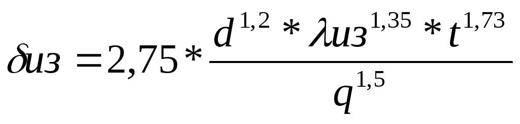 , mm,
, mm,
where d is the diameter of the uninsulated pipeline, mm, d=100mm;
t - temperature of the uninsulated pipeline, ºС, t=180ºС;
λiz - thermal conductivity coefficient of insulation, W/m*K;
q - heat losses per linear meter of pipeline, W/m.
q=0.151 kW/m = 151 W/m²;
λiz=0.0696 W/m²*K.
Slag wool is used as an insulating material.
 =90 mm
The insulation thickness should not exceed 258 mm with a pipe diameter of 100 mm. The resulting δfrom<258 мм.
The diameter of the insulated pipeline will be d=200 mm.
4.2.5 Checking thermal resource savings
Thermal energy is determined by the formula:
t=180-20=160ºС
Figure 4.1 Pipeline diagram
The pipeline area is determined by the formula:
R= 0.050 m, H= 1 m.
F=2*3.14*0.050*1=0.314m²
The heat transfer coefficient of a non-insulated pipeline is determined by the formula:
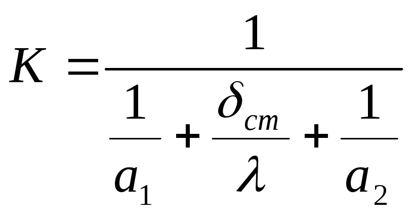 ,
,
where a 1 =1000 W/m²K, a 2 =8 W/m²K, λ=50 W/mK, δst=0.002m.
 =7,93.
Q=7.93*0.314*160=398 W.
The thermal conductivity coefficient of an insulated pipeline is determined by the formula:
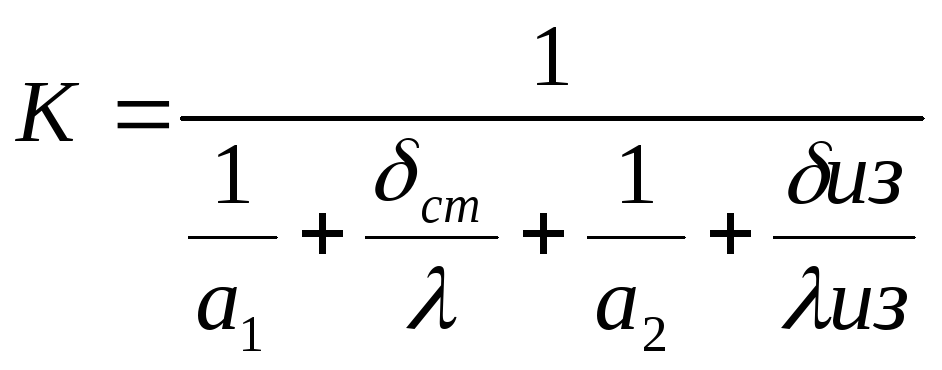 ,
,
where λiz=0.0696 W/mK.
 =2,06
=2,06
The area of the insulated pipeline is determined by the formula F=2*3.14*0.1*1=0.628 m²
Q=2.06*0.628*160=206W.
The calculations showed that when using insulation on a steam pipeline with a thickness of 90 mm, 232 W of thermal energy per 1 m of pipeline is saved, that is, thermal energy is consumed rationally.
4.3 Electrical supply
The main consumers of electricity at the plant are:
Electric lamps (lighting load);
Power supply to the enterprise from the city network through a transformer substation.
The power supply system is three-phase current with an industrial frequency of 50 Hz. Internal network voltage 380/220 V.
Energy consumption:
During peak load hours – 750 kW/h;
Main energy consumers:
Technological equipment;
Power plants;
Enterprise lighting system.
The 380/220V distribution network from distribution cabinets to machine starters is made with LVVR brand cable in steel pipes to the LVP motor wires. The neutral wire of the power supply network is used as grounding.
General (working and emergency) and local (repair and emergency) lighting is provided. Local lighting is powered by low-power step-down transformers at a voltage of 24V. Normal emergency lighting is powered from an electrical network at a voltage of 220V. When the voltage on the substation buses completely disappears, emergency lighting is powered from autonomous sources (“dry batteries”) built into the luminaires or from the AGP.
Working (general) lighting is provided at a voltage of 220V.
Lamps are provided in a design that corresponds to the nature of production and the environmental conditions of the premises in which they are installed. In production premises, they are provided with fluorescent lamps, installed on complete lines from special hanging boxes located at a height of about 0.4 m from the floor.
For evacuation lighting, emergency lighting panels are installed, connected to another (independent) lighting source.
Industrial lighting is provided by fluorescent and incandescent lamps.
Characteristics of incandescent lamps used for lighting industrial premises:
1) 235-240V 100W Base E27
2) 235-240V 200W Base E27
3) 36V 60W Base E27
4) LSP 3902A 2*36 R65IEK
Name of lamps used for lighting refrigeration chambers:
Cold Force 2*46WT26HF FO
For street lighting the following are used:
1) RADBAY 1* 250 WHST E40
2) RADBAY SEALABLE 1* 250WT HIT/ HIE MT/ME E40
Maintenance of electrical power and lighting devices is carried out by a special service of the enterprise.
4.3.1 Calculation of load from process equipment
The type of electric motor is selected from the technological equipment catalog.
R nop, efficiency – passport data of the electric motor, selected from electrical reference books /69/.
R pr - connecting power
P pr =P nom / 
The type of magnetic starter is selected for each electric motor specifically. The calculation of the load from the equipment is summarized in Table 4.4
4.3.2 Calculation of lighting load /69/
Hardware shop
Let's determine the height of the lamps:
H r =H 1 -h St -h r
Where: H 1 - height of premises, 4.8 m;
h st - height of the working surface above the floor, 0.8 m;
h r - the estimated height of the suspension of lamps, 1.2 m.
H p =4.8-0.8-1.2=2.8m
We choose a uniform distribution system of lamps at the corners of the rectangle.
Distance between lamps:
L= (1.2÷1.4) H p
L=1.3·2.8=3.64m
N St = S/L 2 (pcs)
n St =1008/3.64m 2 =74 pcs
We accept 74 lamps.
N l =n St N St
N l =73·2 = 146 pcs
i=A*B/N*(A+B)
where: A - length, m;
B – width of the room, m.
i=24*40/4.8*(24+40) = 3.125
From the ceiling - 70%;
From walls -50%;
From the working surface - 30%.
Q=E min *S*k*Z/N l *η
k - safety factor, 1.5;
N l - number of lamps, 146 pcs.
Q=200*1.5*1008*1.1/146*0.5= 4340 lm
We choose a lamp of the LD-80 type.
Curd shop
Approximate number of lighting lamps:
N St =S/L 2 (pcs)
where: S is the area of the illuminated surface, m2;
L - distance between lamps, m.
n St = 864/3.64 m 2 = 65.2 pcs
We accept 66 lamps.
Determine the approximate number of lamps:
N l =n St N St
N St - number of lamps in the lamp
N l =66·2 = 132 pcs
Let's determine the coefficient of luminous flux utilization using the coefficient table:
i=A*B/N*(A+B)
where: A - length, m;
B – width of the room, m.
i=24*36/4.8*(24+36) = 3
We accept light reflection coefficients:
From the ceiling - 70%;
From walls -50%;
From the working surface - 30%.
Based on the room index and reflection coefficient, we select the luminous flux utilization factor η=0.5
Let's determine the luminous flux of one lamp:
Q=E min *S*k*Z/N l *η
where: E min - minimum illumination, 200 lux;
Z – linear illumination coefficient 1.1;
k - safety factor, 1.5;
η – luminous flux utilization factor, 0.5;
N l - number of lamps, 238 pcs.
Q=200*1.5*864*1.1/132*0.5 = 4356 lm
We choose a lamp of the LD-80 type.
Whey processing workshop
n St =288/3.64 2 =21.73 pcs
We accept 22 lamps.
Number of lamps:
i=24*12/4.8*(24+12) =1.7
Luminous flux of one lamp:
Q=200*1.5*288*1.1/56*0.5=3740 lux
We choose a lamp of the LD-80 type.
Reception department
Approximate number of lamps:
n St =144/3.64m 2 =10.8 pcs
We accept 12 lamps
Number of lamps:
Luminous flux utilization factor:
i=12*12/4.8*(12+12)=1.3
Luminous flux of one lamp:
Q=150*1.5*144*1.1/22*0.5=3740 lux
We choose a lamp of the LD-80 type.
The installed power of one lighting load is Р=N 1 *Р l (W)
Calculation of lighting load using the specific power method.
E min =150 lux W*100=8.2 W/m 2
Conversion to illumination of 150 lux is carried out according to the formula
W= W*100* E min /100, W/m 2
W= 8.2*150/100 = 12.2 W/m2
Determination of the total power required for lighting (P), W.
Hardware shop P= 12.2*1008= 11712 W
Curd shop P= 12.2*864= 10540 W
Reception department Р=12.2*144= 1757 W
Whey processing shop P= 12.2* 288= 3514 W
Determine the number of capacities N l = P/P 1
P 1 – power of one lamp
N l (hardware shop) = 11712 / 80 = 146
N l (curd shop) = 10540 / 80 = 132
N l (reception department) = 1756/ 80 = 22
N l (whey processing workshop) = 3514/80 = 44
146+132+22+44= 344; 344*80= 27520 W.
Table 4.5 – Calculation of power load
|
Equipment identification |
Type, brand |
Quantity |
Motor type |
Power |
Electric motor efficiency - |
Magnet type new start |
|
|
Nominal R |
Electric R |
||||||
|
Mixer | |||||||
|
Filling machine |
Dispenser YA1-DT-1 | ||||||
|
Filling machine | |||||||
|
Filling machine | |||||||
|
Creative production line | |||||||


Table 4.6 – Calculation of lighting load
|
Name of premises |
Min. lighting |
Lamp type |
Number of lamps |
Electrical kW |
Specific power, W/m 2 |
|
|
Reception department | ||||||
|
Curd shop | ||||||
|
Hardware shop | ||||||
|
Whey processing workshop |
4.3.3 Test calculation of power transformers
Active power: P tr = P max / η network
where: P max = 144.85 kW (according to the graph “Power consumption by hour of day”)
η network =0.9
R tr =144.85/0.9=160.94 kW
Apparent power, S, kVA
S=P tr/cosθ
S=160.94/0.8=201.18 kVA
For the transformer substation TM-1000/10, the total power is 1000 kVA, the total power with the existing load at the enterprise is 750 kVA, but taking into account the technical re-equipment of the curd section and the organization of whey processing, the required power should be: 750 + 201.18 = 951 .18 kVA< 1000кВ·А.
Electricity consumption per 1 ton of produced products:
R  =
=
where M  - mass of all produced products, t;
M  =28.675 t
R  =462.46/28.675=16.13 kW*h/t
Thus, from the graph of electricity consumption by hour of the day it is clear that the greatest power is required in the time interval from 8:00 to 11:00 and from 16:00  until 21
  hours. During this period of time, incoming raw milk is received and processed, products are produced, and drinks are bottled. Small jumps are observed from 8
  until 11
  , when most of the processing of milk to produce products takes place.
4.3.4 Calculation of cross sections and selection of cables.
The cable cross-section is determined by voltage loss
S=2 PL*100/γ*ζ*U 2, where:
L – cable length, m.
γ – copper conductivity, OM * m.
ζ – permissible voltage loss,%
U - network voltage, V.
S= 2*107300*100*100 / 57.1*10 3 *5*380 2 =0.52 mm 2 .
Conclusion: the cross-section of the VVR brand cable used by the enterprise is 1.5 mm 2 - therefore, the existing cable will provide the areas with electricity.
Table 4.7 – Hourly electricity consumption for product production
|
Hours of the day |
||||||||||||||||||||||||||||||||||
|
Pump 50-1TS7,1-31 | ||||||||||||||||||||||||||||||||||
|
Counter Vzlet-ER | ||||||||||||||||||||||||||||||||||
|
Cooler | ||||||||||||||||||||||||||||||||||
|
Pump G2-OPA | ||||||||||||||||||||||||||||||||||
|
PPOU TsKRP-5-MST | ||||||||||||||||||||||||||||||||||
|
Separator-normalizer OSCP-5 | ||||||||||||||||||||||||||||||||||
|
Flow meter | ||||||||||||||||||||||||||||||||||
|
Curd maker TI | ||||||||||||||||||||||||||||||||||
|
Continuation of Table 4.7 |
||||||||||||||||||||||||||||||||||
|
Hours of the day |
||||||||||||||||||||||||||||||||||
|
Diaphragm pump | ||||||||||||||||||||||||||||||||||
|
Dehydrator | ||||||||||||||||||||||||||||||||||
|
Stabilizer parameters | ||||||||||||||||||||||||||||||||||
|
Pump P8-ONB-1 | ||||||||||||||||||||||||||||||||||
|
Filling machine SAN/T | ||||||||||||||||||||||||||||||||||
|
Chopper-mixer-250 | ||||||||||||||||||||||||||||||||||
|
Filling machine | ||||||||||||||||||||||||||||||||||
|
Minced meat mixer | ||||||||||||||||||||||||||||||||||
|
Continuation of Table 4.7 |
||||||||||||||||||||||||||||||||||
|
Hours of the day |
||||||||||||||||||||||||||||||||||
|
Separator- Clarifier | ||||||||||||||||||||||||||||||||||
|
VDP bath | ||||||||||||||||||||||||||||||||||
|
Metering pump NRDM | ||||||||||||||||||||||||||||||||||
|
Installation | ||||||||||||||||||||||||||||||||||
|
VDP bath | ||||||||||||||||||||||||||||||||||
|
Submersible pump Seepex | ||||||||||||||||||||||||||||||||||
|
Tubular pasteurizer | ||||||||||||||||||||||||||||||||||
|
Continuation of Table 4.7 |
||||||||||||||||||||||||||||||||||
|
Hours of the day |
||||||||||||||||||||||||||||||||||
|
Filling machine | ||||||||||||||||||||||||||||||||||
|
Reception department | ||||||||||||||||||||||||||||||||||
|
Hardware shop | ||||||||||||||||||||||||||||||||||
|
Curd shop | ||||||||||||||||||||||||||||||||||
|
Whey processing workshop | ||||||||||||||||||||||||||||||||||
|
End of table 4.7 |
||||||||||||||||||||||||||||||||||
|
Hours of the day |
||||||||||||||||||||||||||||||||||
|
Unaccounted losses 10% | ||||||||||||||||||||||||||||||||||

Electricity consumption chart.
