Nodes of portal connections. Bonds in coverages
|
Links are important elements steel frame required to meet the following requirements: – ensuring the immutability of the frame spatial system and the stability of its compressed elements; - perception and transfer to the foundations of some loads (wind, horizontal from cranes); – ensuring collaboration transverse frames at local loads (for example, crane); – creation of frame rigidity necessary to ensure normal conditions operation; – providing conditions for high-quality and convenient installation. Links are divided into links between columns and links between trusses (cover links). |
Links between columns.
The system of connections between columns (9.8) provides during operation and installation:
– geometric immutability of the frame;
- the bearing capacity of the frame and its rigidity in the longitudinal direction;
- the perception of longitudinal loads from the wind in the end of the building and braking of the crane bridge;
– stability of columns from the plane of transverse frames.
To perform these functions, at least one vertical HDD along the length of the temperature block and a system of longitudinal elements attaching columns that are not included in the hard disk to the latter. The hard disks (Fig. 11.5) include two columns, a crane beam, horizontal braces and a lattice, which ensures geometric invariability when all elements of the disk are hinged.
The lattice is designed cross (Fig. 9.13, a), the elements of which are accepted as flexible [] = 220 and work in tension in any direction of forces transmitted to the disk (the compressed brace loses stability) and triangular (Fig. 9.13, b), the elements of which work in tension and compression. The lattice scheme is chosen so that its elements can be conveniently attached to the columns (the angles between the vertical and the lattice elements are close to 45 °). With large column pitches in the lower part of the column, it is advisable to arrange a disk in the form of a double-hinged lattice frame, and in the upper part - the use of a truss truss (Fig. 9.13, c). Spacers and grating at low heights of the column section (for example, in the upper part) are located in one plane, and at high heights (lower part of the column) - in two planes.
Rice. 9.13. Schemes of designs of hard disks of connections between columns:
a - while ensuring the stability of the lower part of the columns from the plane of the frame; b - if necessary, install intermediate struts; c - if it is necessary to use a crane gauge.

Rice. 9.14. Schemes of temperature movements and forces:
a - at the location of vertical bonds
in the middle of the frame; b - the same, at the ends of the frame
When placing hard disks (connection blocks) along the building, it is necessary to take into account the possibility of column movements during thermal deformations of the longitudinal elements (Fig. 9.14, a). If you put the disks on the ends of the building (Fig. 9.14, b), then in all longitudinal elements (crane structures, truss trusses, bracing braces) and in the braces, significant temperature forces arise.
Therefore, with a small length of the building (temperature block), a vertical connection is placed in one panel (Fig. 9.15, a). With a long building length, vertical connections are placed in two panels (Fig. 9.15, b), and the distance between their axes should be such that the forces F t are small. The limiting distances between the disks depend on possible temperature differences and are established by the standards (Table 9.3).
At the ends of the building, the extreme columns are interconnected by flexible upper connections (see Fig. 9.15, a). Due to the relatively low rigidity of the overhead part of the column, the location of the upper connections in the end panels has little effect on thermal stresses.
Vertical connections between columns are placed along all rows of columns of the building; they should be placed between the same axes.
Rice. 9.15. Location of connections between columns in buildings:
a - short (or temperature compartments); b - long; 1 - columns; 2 - spacers; 3 - axis of expansion joint; 4- crane beams; 5 - communication block; 6- temperature block; 7 - bottom farms; 8 - shoe bottom
Table9.3. Limit dimensions between vertical connections, m
When designing connections along the middle rows of columns in the crane runway, it should be borne in mind that quite often, according to the conditions of technology, it is necessary to have free space between the columns. In these cases, portal connections are constructed (see Fig. 11.5, c).
The connections installed within the height of the crossbars in the connection and end blocks are designed in the form of independent trusses (mounting element), spacers are placed in other places.
The longitudinal elements of the connections at the points of attachment to the columns ensure that these points are not displaced from the plane of the transverse frame. These points in the calculation scheme of the column can be taken by hinged supports. When the height of the lower part of the column is high, it may be advisable to install an additional spacer, which fixes the lower part of the column in the middle of its height and reduces the estimated length of the column.
Rice. 9.16. The work of connections between columns under the influence of: a - wind load on the end of the building; b - overhead cranes.
Load transfer. At point A (Fig. 9.16, a), the flexible bond element 1 cannot perceive the compressive force, therefore F w is transmitted by a shorter and rather rigid spacer 2 to point B. Here, the force through element 3 is transmitted to point C. At this point, the force is perceived by crane beams 4, transmitting the force F w to the connection block at point G. The connections work similarly on the forces of the longitudinal effects of cranes F (Fig. 9.16, b).
Connection elements are made of angles, channels, rectangular and round pipes. With a large length of connection elements that perceive small forces, they are calculated according to the ultimate flexibility, which for compressed connection elements below the crane beam is 210 - 60 ( is the ratio of the actual force in the connection element to its bearing capacity), above - 200; for stretched ones, these values are 200 and 300, respectively.
Coverage Links (9.9).
Horizontal links are located in the planes of the lower and upper chords of the trusses and the upper chord of the lantern. Horizontal connections consist of transverse and longitudinal (Fig. 9.17 and 9.18).
Rice. 9.17. Links between farms: a - along the upper belts of farms; b - along the lower belts of farms; c - vertical; / - spacer in the ridge; 2 - transverse braced trusses
Rice. 9.18. Connections between lanterns
The elements of the upper chord of the roof trusses are compressed, so it is necessary to ensure their stability from the plane of the trusses. Ribs of roofing plates and purlins can be considered as supports that prevent the displacement of the upper nodes from the plane of the truss, provided that they are secured from longitudinal movements with braces.
Need to pay Special attention for tying truss knots within the lantern, where there is no roofing. Here, to unfasten the nodes of the upper chord of the trusses from their plane, spacers are provided, and such spacers in the ridge node of the truss are required (Fig. 9.19, b). Spacers are attached to the end connections in the plane of the upper chords of the trusses.
During installation (before the installation of roof slabs or girders), the flexibility of the upper chord from the plane of the truss should not exceed 220. If the ridge strut does not provide this condition, an additional strut is placed between it and the strut in the plane of the columns.
In buildings with overhead cranes, it is necessary to ensure the horizontal rigidity of the frame both across and along the building. During the operation of overhead cranes, forces arise that cause transverse and longitudinal deformations of the shop frame. If the transverse rigidity of the frame is insufficient, the cranes may jam during movement, and their normal operation is disrupted. Excessive vibrations of the frame create unfavorable conditions for the operation of cranes and the safety of enclosing structures. Therefore, in single-span buildings of great height ( H 0 > 18 m), in buildings with overhead cranes with a lifting capacity ( Q≥ 10 t, with cranes of heavy and very heavy duty at any load capacity, a system of longitudinal ties along the lower chords of trusses is required.
Rice. 9.19. Cover link work:
a - diagram of the operation of horizontal connections under the action of external loads; b and c "- the same, with conditional forces from the loss of stability of the truss belts; / - ties along the lower truss belts; 2 - the same, along the top; 3 - bracing of the ties; 4 - stretching of the ties; 5 - form of buckling or oscillation in the absence of spacers (stretch marks); 6 - the same, in the presence of spacers.
Horizontal forces from overhead cranes act in the transverse direction on one flat frame and two or three adjacent ones. Longitudinal connections ensure the joint operation of the system of flat frames, as a result of which the transverse deformations of the frame from the action of a concentrated force are significantly reduced (Fig. 9.19, a).
The rigidity of these links must be sufficient to involve adjacent frames in the work, and their width is assigned equal to the length of the first panel of the lower chord of the truss. Connections are usually installed on bolts. Welding of bonds increases their rigidity several times.
The panels of the lower chord of trusses adjacent to the supports, especially when the crossbar is rigidly connected to the column, can be compressed, in this case the longitudinal braces ensure the stability of the lower chord from the plane of the trusses. The transverse ties fix the longitudinal ones, and at the ends of the building they are also necessary for the perception of the wind load directed at the end of the building.
Fachwerk racks transmit the wind load F w to the nodes of the transverse horizontal end truss, the belts of which are the lower belts of the end and adjacent truss trusses (see Fig. 9.19, a). The support reactions of the end truss are perceived by vertical connections between the columns and are transferred to the foundation (see Fig. 9.19). In the plane of the lower chords, intermediate cross braces are also arranged, located in the same panels as the cross braces along the upper truss chords.
To avoid vibration of the lower chord of trusses due to the dynamic action of overhead cranes, it is necessary to limit the flexibility of the stretched part of the lower chord from the plane of the frame. In order to reduce the free length of the stretched part of the lower chord, in some cases it is necessary to provide braces that secure the lower chord in the lateral direction. These extensions perceive the conditional transverse force Q fic (Fig. 9.19, c).
In long buildings consisting of several temperature blocks, cross-braced trusses along the upper and lower chords are placed at each expansion joint (as at the ends), bearing in mind that each temperature block is a complete spatial complex.
Vertical links between trusses are installed in the same axes in which horizontal cross braces are placed (see Fig. 9.20, c). Vertical connections are placed in the plane of the truss struts in the span and on the supports (when the trusses are supported at the level of the lower chord). In the span, one or two vertical connections are installed along the width of the span (in 12-15 m). Vertical ties give immutability to the spatial block, consisting of two truss trusses and horizontal cross ties along the upper and lower chords of the trusses. Rafter trusses have a slight lateral rigidity, therefore, during installation, they are fixed to a rigid spatial block with spacers.
In the absence of horizontal transverse ties along the upper chords, to ensure the rigidity of the spatial block and fix the upper chords from the plane, vertical ties are installed after 6 m (Fig. 9.20, e).
Rice. 9.20. Schemes of communication systems by coverage:
a - cross connections with a 6-meter step of frames; b - connections with a triangular lattice; c and d - the same, with a 12-meter frame step; e - a combination of horizontal ties along the lower chords of trusses with vertical ties; I, II - connections, respectively, on the upper and lower chords of farms
The sections of the connection elements depend on their design scheme and the pitch of the truss trusses. For horizontal connections with a truss pitch of 6 m, a cross or triangular lattice is used (Fig. 9.20, a, b). The braces of the cross lattice work only in tension, and the posts work in compression. Therefore, racks are usually designed from two corners of the cross section, and braces - from single corners. The elements of a triangular lattice can be both compressed and stretched, so they are usually designed from bent profiles. Triangular ties are somewhat heavier than cross ties, but their installation is easier.
With a truss pitch of 12 m, the diagonal elements of the connections, even in the cross lattice, are very heavy. Therefore, the system of connections is designed so that the longest element is no more than 12 m, diagonals support these elements (Fig. 9.20, c). On fig. 9.20, d shows the diagram of connections, where the diagonal elements fit into a square 6 m in size and rely on longitudinal elements 12 m long, which serve as belts of truss trusses. These elements have to be made of a composite section or from bent profiles.
Vertical connections between trusses and lanterns are best done in the form of separate transportable trusses, which is possible if their height is less than 3900 mm. Various schemes of vertical connections are shown in fig. 9.20, e.
On fig. 9.19 shows the signs of the forces arising in the elements of the pavement ties for a certain direction of the wind load, local horizontal forces and conditional transverse forces. Many link elements can be compressed or stretched. In this case, their section is selected according to the worst case - according to the flexibility for the compressed elements of the connections.
Spacers in the ridge of the upper chord of the trusses (element 3 in Fig. 9.19, b) ensure the stability of the upper chord from the plane of the trusses both during operation and during installation. In the latter case, they are attached to only one cross-link, their cross section is selected based on compression.
2.3.2. Links between columns
The purpose of the connections: 1) the creation of the longitudinal rigidity of the frame, necessary for its normal operation; 2) ensuring the stability of the columns from the plane of the transverse frames; 3) the perception of the wind load acting on the end walls of the building, and the longitudinal inertial effects of overhead cranes.
Connections are established along all longitudinal rows of building columns. Schemes of vertical connections between columns are given in Fig. 2.34. Schemes (Fig. 2.34, c, d, f) refer to buildings without cranes or with overhead crane equipment, all the rest - to buildings equipped with overhead cranes.
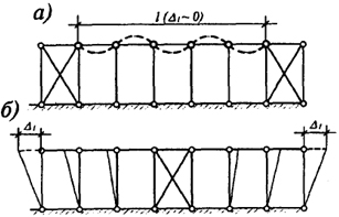
In buildings equipped with overhead cranes, the main ones are the lower vertical connections. They, together with two columns, crane beams and foundations (Fig. 2.34 d, f...l) form geometrically invariable discs fixed in the longitudinal direction. The freedom or constraint of deformation of other frame elements attached to such disks depends significantly on the number of rigid blocks and their location along the frame. If you place the communication blocks at the ends of the temperature compartment (Fig. 2.35, a), then with an increase in temperature and the absence of freedom of deformation ( t 0) loss of stability of the compressed elements is possible. That is why it is better to place vertical connections in the middle of the temperature block (Fig. 2.34, a...in, rice. 2.35 b), providing freedom of temperature movements on both sides of the connection block (Δ t 0) and eliminating the appearance of additional stresses in the longitudinal elements of the frame. At the same time, the distance from the end of the building (compartment) to the axis of the nearest vertical connection and the distance between the connections in one compartment should not exceed the values \u200b\u200bgiven in Table. 1.2.
In the overhead part of the columns, vertical connections should be provided at the ends of the temperature blocks and at the locations of the lower vertical connections (see Fig. 2.34 a, in). The expediency of installing top connections at the ends of the building is due, first of all, to the need to create the shortest path for transferring the wind load Rw on the end of the building along the longitudinal tie elements or crane beams on the foundations (Fig. 2.36). This load is equal to the support reaction of a horizontal truss truss (see Fig. 2.30) or two trusses in multi-span
Rice. 2.35. Influence of layouts of connection blocks on the development of temperature deformations:
a- when the connection blocks are located at the ends; b- the same, in the middle of the building
buildings. Similarly, forces from longitudinal braking of cranes are transferred to the foundations F cr(Fig. 2.36). The calculated longitudinal braking force is taken from two cranes of one or adjacent spans. In long buildings, these force effects are distributed equally to all vertical braced trusses between columns within the temperature block.
The constructive scheme of connections depends on the pitch of the columns and the height of the building. Various options for solving links are shown in Fig. 2.34. The most common is the cross scheme (Fig. 2.34, Mrs.), as it provides the simplest and most rigid tying of building columns. The number of panels in height is assigned in accordance with the recommended angle of inclination of the braces to the horizontal (α = 35°...55°). If it is necessary to use the space between the columns, which is often due to the technological process, the connections of the lower tier are designed portal (Fig. 2.34 to) or semi-portal (see Fig. 2.34, l).
Vertical connections between columns are also used for fixing spacers in nodes (Fig. 2.34 e...and), if they are provided to reduce the effective lengths of the columns from the planes of the frames.
In columns with a constant section height h≤ 600 mm, connections are placed in the plane of the axes of the columns; in stepped communication columns above
Rice. 2.36. Schemes of transmission of wind (from the end of the building) and longitudinal crane loads:
a, b- buildings with overhead cranes; c, g- buildings with overhead cranes
brake structure (upper vertical connections) with h≤ 600 mm are installed along the axes of the columns, below the crane beam (lower vertical ties) when h> 600 mm - in the plane of each shelf or column branch. Connection nodes between columns are shown in fig. 2.37.
The connections are fastened on bolts of coarse or normal accuracy, and after the alignment of the columns, they can be welded to the packings. In buildings with overhead cranes of the 6K ... 8K operating mode groups, the gussets of the connections should be scalded or connections made on high-strength bolts.
When calculating links, you can use the recommendations of clause 6.5.1.
At the very beginning of my career, I had neither experienced mentors, nor friends and acquaintances working in large design offices who could explain to me my questions about metal structures. Since I still consider myself a novice engineer, I do not claim that my entry will be an authoritative source. I am ready to make changes to my article based on the results of the discussion.
I was inspired to write the article by the fact that I could not at one time find a detailed step-by-step description of the SNiP method for selecting links, and what was stated in the SNiP itself was not clear to me.
So, we have a connection panel between the columns, the spacing of the columns is 6 m, the height of the columns is 8 m, there is no crane. Task: select the section of the elements of the cross connection and select the node of intersection of the connection branches.
In the vast majority of "sheds", it is enough to select the cross-sections of vertical connections between columns according to the criterion of not exceeding the limiting flexibility.
Clause 15.4.12 of SP 16 tells us:
When using a cross lattice of coating bonds, with the exception of
buildings and structures of the I level of responsibility, calculation according to the conditional scheme is allowed
assuming that the braces perceive only tensile forces.
Which, as it were, hints: "Do not do this in vertical connections between columns (do not turn off the compressed branch from the calculation), because nothing similar has been written about vertical connections between columns"
The hint is clear, so we move on to Section 10.4.1. SP 16, which states that the flexibility of the compressed elements (in our case, one of the branches will always be compressed) should not exceed the limit values \u200b\u200bgiven in Table 32. And the stretched ones (one of the branches will always be stretched) - in Table 33. Since horizontal load can be applied to the connection block both from one side and from the other, both of our connection branches can be compressed, so for now we will use only table 32, namely item 6 of this table, which says that the limit flexibility of elements of vertical connections between columns λ u =200.
As is known, the actual flexibility of the element "λ" is directly proportional to the calculated length of the element "L ef " and inversely proportional to the radius of gyration of the cross section of the element "i". λ = L ef / i
To begin with, let's deal with the estimated length, for this we go to clause 10.1.1 and look at Figure 13 e) - why not our circuit that fell on its side?
As the initial data for our vertical connections between the columns, let's take a section from a closed rectangular pipe.
1. So, the first line the first column - both elements are not interrupted. Such a case is possible when using corners or channels as connection elements, which, as it were, is not our case, but we will consider it anyway. L ef \u003d l \u003d l 1 \u003d 10000 / 2 \u003d 5000 (mm). The calculated length of the considered compressed branch is equal to the distance from the attachment point to the column to the point of intersection with the supporting tension element.
2. Second row first column. The considered compressed element is not interrupted, the supporting element is stretched and interrupted. This case suits us well. L ef \u003d 0.7 * l 1 \u003d 0.7 * 10000 \u003d 7000 (mm). The supporting stretch element is not as "good" as in claim 1. but still good, therefore it reduces the estimated length of the element in question compared to the geometric length by 30%.
3. Third line first column. Due to the fact that the supporting element is stretched, the compressed one did not even notice that it was interrupted at the point of intersection of the braces. Estimated length is the same as in paragraph 2.
4. First row second column. Such a situation is possible, for example, when removing the braces along the top of the columns from the scheme. The supporting element reduces the calculated length of the considered compressed element by 30%.
5. Second row, second column. The compressed element in question is supported by the non-working discontinuous element. In this case, the supporting element does not support anything (it does not affect the element under consideration), therefore the calculated length of the considered compressed element is equal to the geometric length between the points of attachment to the columns.
6. Third row, second column. The compressed element in question is interrupted, and the supporting one did not even think to support it - we get a mechanism. Table 25 tells us authoritatively that this should not be done.
7. First row third column. Such a case is possible when the vertical connections between the columns are compressed. Compression occurs when welding or bolts of accuracy class A are used in the attachment unit to the column. Also, this situation corresponds to the case when compression is not taken into account - the element in question is stretched, and the supporting element is compressed (the elements have changed places compared to paragraph 1). Here, the supporting element, although compressed, does not interfere with the work of the element in question. Compared with paragraph 1. the estimated length will increase by 2 times, but also the ultimate flexibility for tensioned elements of vertical connections between columns in accordance with Table 33 of SP 16 λ u = 400 (increased by 2 times).
8. Second row, third column. Such a situation is possible in the same cases as in paragraph 7. But here, the already supporting interrupted communication branch worsens the operation of the element in question. We do not take into account compression in our "sheds", therefore, the estimated length of the considered stretched element L ef \u003d 10000 * 1.4 \u003d 14000 (2 times more than in paragraph 2.). The limiting flexibility, as well as in item 7, is 2 times greater than λ u = 400.
9. Third line, third column. Table 25, as in paragraph 6, does not wish to provide clarification for this case.
For our initial data, 2 cases are suitable - item 2 and item 8, because it is difficult to cross pipes and connect them to each other at the point of intersection, while not interrupting either of them, and we are embarrassed to interrupt both.
According to paragraph 2 L ef = 7000 (mm), λ u = 200 (the element under consideration is compressed), λ = L ef / i, we take λ = λ u and express the radius of gyration from here (the required radius of gyration, which will provide flexibility no higher than marginal)
i = L ef / λ = 7000 / 200 = 35 (mm)
according to clause 8 L ef = 14000 (mm), λ u = 400 (the element under consideration is stretched)
i= L ef / λ = 14000 / 400 = 35(mm)
And now let's go back to our original diagram and try to just turn off the compressed branch from the calculation, just assume that only the stretched branch of the connection works.
L ef = 10000 (mm)
i = L ef / λ = 10000 / 400 = 25 (mm)
Conclusion: when selecting the section of branches of cross vertical connections between columns, under certain circumstances, it makes no difference whether you consider a compressed element or a stretched one - the result will be the same. At the same time, it is not necessary to select the sections of the elements of vertical connections on the assumption that the compressed branch is "turned off".
Thank you for your attention. Paper will endure everything (" Epistola non erubescit" - Cicero)
P.S. I hope the article was useful at least because you now know who said: "Paper will endure everything."
|
Ties are important elements of the steel frame, which are necessary to fulfill the following requirements: – ensuring the immutability of the frame spatial system and the stability of its compressed elements; - perception and transfer to the foundations of some loads (wind, horizontal from cranes); - ensuring the joint operation of transverse frames under local loads (for example, crane); - creation of frame rigidity necessary to ensure normal operating conditions; – providing conditions for high-quality and convenient installation. Links are divided into links between columns and links between trusses (cover links). |
Links between columns.
The system of connections between columns (9.8) provides during operation and installation:
– geometric immutability of the frame;
- the bearing capacity of the frame and its rigidity in the longitudinal direction;
- the perception of longitudinal loads from the wind in the end of the building and braking of the crane bridge;
– stability of columns from the plane of transverse frames.
To perform these functions, at least one vertical hard disk is required along the length of the temperature block and a system of longitudinal elements attaching columns that are not included in the hard disk to the latter. The hard disks (Fig. 11.5) include two columns, a crane beam, horizontal braces and a lattice, which ensures geometric invariability when all elements of the disk are hinged.
The lattice is designed cross (Fig. 9.13, a), the elements of which are accepted as flexible [] = 220 and work in tension in any direction of forces transmitted to the disk (the compressed brace loses stability) and triangular (Fig. 9.13, b), the elements of which work in tension and compression. The lattice scheme is chosen so that its elements can be conveniently attached to the columns (the angles between the vertical and the lattice elements are close to 45 °). With large column pitches in the lower part of the column, it is advisable to arrange a disk in the form of a double-hinged lattice frame, and in the upper part - the use of a truss truss (Fig. 9.13, c). Spacers and grating at low heights of the column section (for example, in the upper part) are located in one plane, and at high heights (lower part of the column) - in two planes.
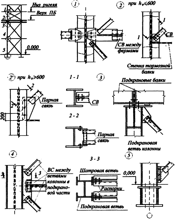
Rice. 9.13. Schemes of designs of hard disks of connections between columns:
a - while ensuring the stability of the lower part of the columns from the plane of the frame; b - if necessary, install intermediate struts; c - if it is necessary to use a crane gauge.
Rice. 9.14. Schemes of temperature movements and forces:
a - at the location of vertical bonds
in the middle of the frame; b - the same, at the ends of the frame
When placing hard disks (connection blocks) along the building, it is necessary to take into account the possibility of column movements during thermal deformations of the longitudinal elements (Fig. 9.14, a). If you put the disks on the ends of the building (Fig. 9.14, b), then in all longitudinal elements (crane structures, truss trusses, bracing braces) and in the braces, significant temperature forces arise.
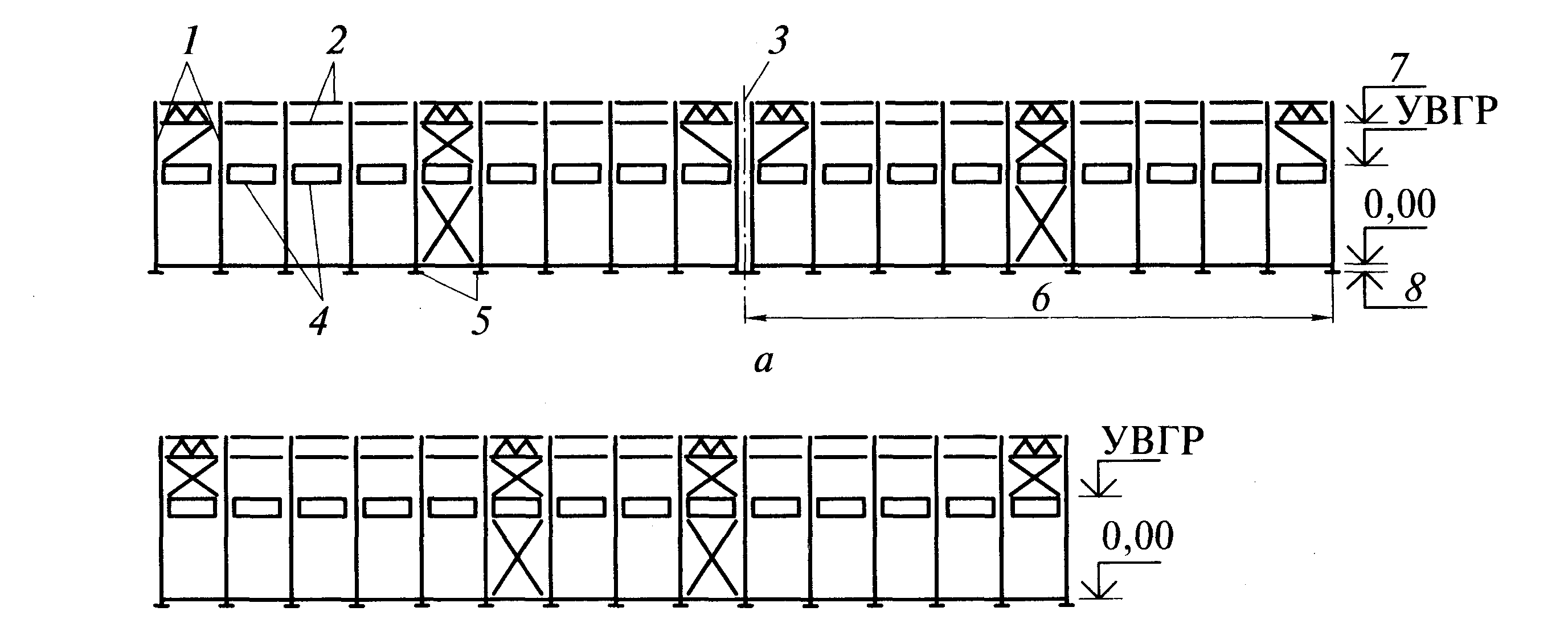
Therefore, with a small length of the building (temperature block), a vertical connection is placed in one panel (Fig. 9.15, a). With a long building length, vertical connections are placed in two panels (Fig. 9.15, b), and the distance between their axes should be such that the forces F t are small. The limiting distances between the disks depend on possible temperature differences and are established by the standards (Table 9.3).
At the ends of the building, the extreme columns are interconnected by flexible upper connections (see Fig. 9.15, a). Due to the relatively low rigidity of the overhead part of the column, the location of the upper connections in the end panels has little effect on thermal stresses.
Vertical connections between columns are placed along all rows of columns of the building; they should be placed between the same axes.
Rice. 9.15. Location of connections between columns in buildings:
a - short (or temperature compartments); b - long; 1 - columns; 2 - spacers; 3 - axis of expansion joint; 4- crane beams; 5 - communication block; 6- temperature block; 7 - bottom farms; 8 - shoe bottom
Table9.3. Maximum dimensions between vertical ties, m
When designing connections along the middle rows of columns in the crane runway, it should be borne in mind that quite often, according to the conditions of technology, it is necessary to have free space between the columns. In these cases, portal connections are constructed (see Fig. 11.5, c).
The connections installed within the height of the crossbars in the connection and end blocks are designed in the form of independent trusses (mounting element), spacers are placed in other places.
The longitudinal elements of the connections at the points of attachment to the columns ensure that these points are not displaced from the plane of the transverse frame. These points in the calculation scheme of the column can be taken by hinged supports. When the height of the lower part of the column is high, it may be advisable to install an additional spacer, which fixes the lower part of the column in the middle of its height and reduces the estimated length of the column.
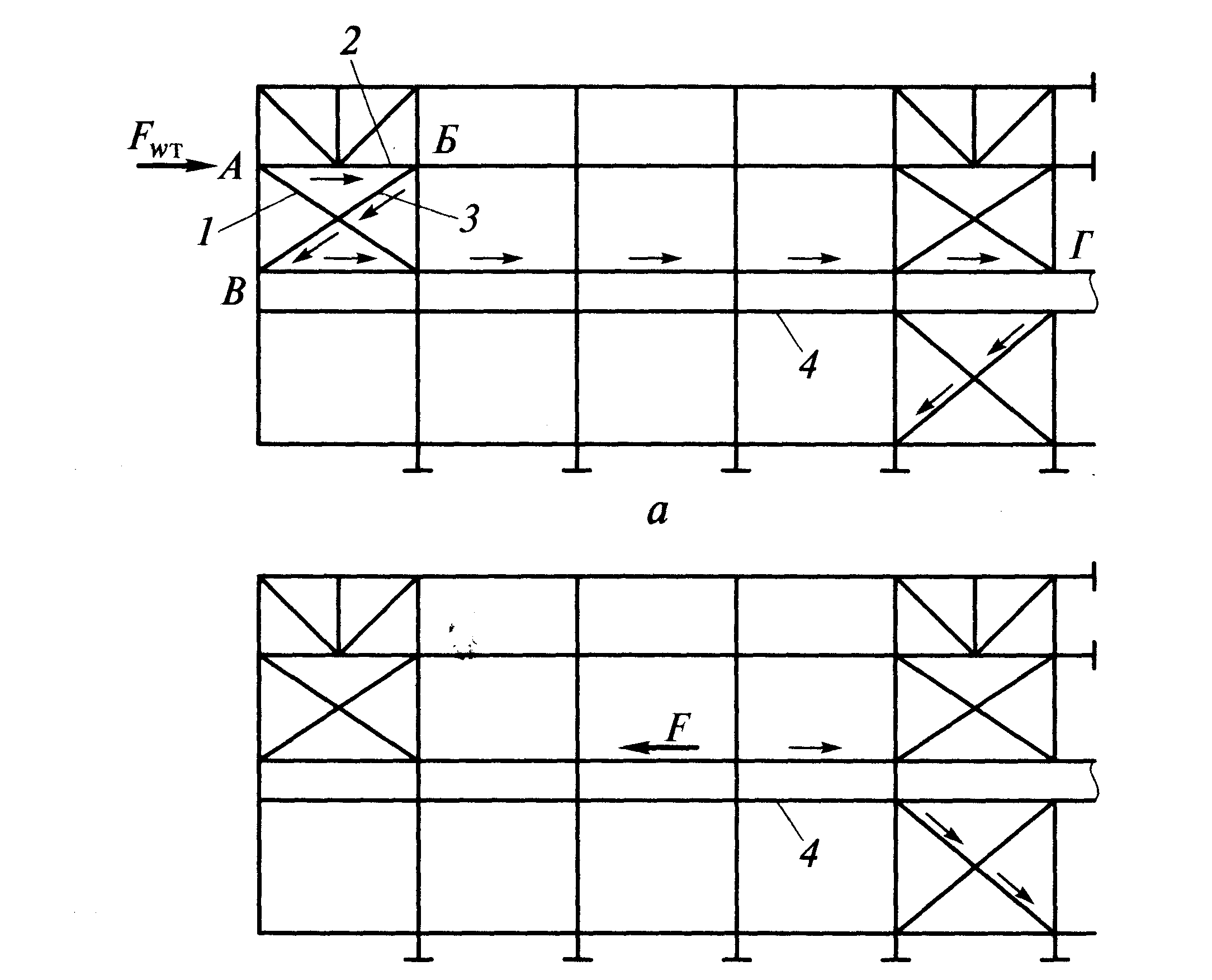
Rice. 9.16. The work of connections between columns under the influence of: a - wind load on the end of the building; b - overhead cranes.
Load transfer. At point A (Fig. 9.16, a), the flexible bond element 1 cannot perceive the compressive force, therefore F w is transmitted by a shorter and rather rigid spacer 2 to point B. Here, the force through element 3 is transmitted to point C. At this point, the force is perceived by crane beams 4, transmitting the force F w to the connection block at point G. The connections work similarly on the forces of the longitudinal effects of cranes F (Fig. 9.16, b).
Connection elements are made of angles, channels, rectangular and round pipes. With a large length of connection elements that perceive small forces, they are calculated according to the ultimate flexibility, which for compressed connection elements below the crane beam is 210 - 60 ( is the ratio of the actual force in the connection element to its bearing capacity), above - 200; for stretched ones, these values are 200 and 300, respectively.
Coverage Links (9.9).
Horizontal links are located in the planes of the lower and upper chords of the trusses and the upper chord of the lantern. Horizontal connections consist of transverse and longitudinal (Fig. 9.17 and 9.18).
Rice. 9.17. Links between farms: a - along the upper belts of farms; b - along the lower belts of farms; c - vertical; / - spacer in the ridge; 2 - transverse braced trusses
Rice. 9.18. Connections between lanterns
The elements of the upper chord of the roof trusses are compressed, so it is necessary to ensure their stability from the plane of the trusses. Ribs of roofing plates and purlins can be considered as supports that prevent the displacement of the upper nodes from the plane of the truss, provided that they are secured from longitudinal movements with braces.
It is necessary to pay special attention to the tying of truss knots within the lantern, where there is no roofing. Here, to unfasten the nodes of the upper chord of the trusses from their plane, spacers are provided, and such spacers in the ridge node of the truss are required (Fig. 9.19, b). Spacers are attached to the end connections in the plane of the upper chords of the trusses.
During installation (before the installation of roof slabs or girders), the flexibility of the upper chord from the plane of the truss should not exceed 220. If the ridge strut does not provide this condition, an additional strut is placed between it and the strut in the plane of the columns.
In buildings with overhead cranes, it is necessary to ensure the horizontal rigidity of the frame both across and along the building. During the operation of overhead cranes, forces arise that cause transverse and longitudinal deformations of the shop frame. If the transverse rigidity of the frame is insufficient, the cranes may jam during movement, and their normal operation is disrupted. Excessive vibrations of the frame create unfavorable conditions for the operation of cranes and the safety of enclosing structures. Therefore, in single-span buildings of great height ( H 0 > 18 m), in buildings with overhead cranes with a lifting capacity ( Q≥ 10 t, with cranes of heavy and very heavy duty at any load capacity, a system of longitudinal ties along the lower chords of trusses is required.
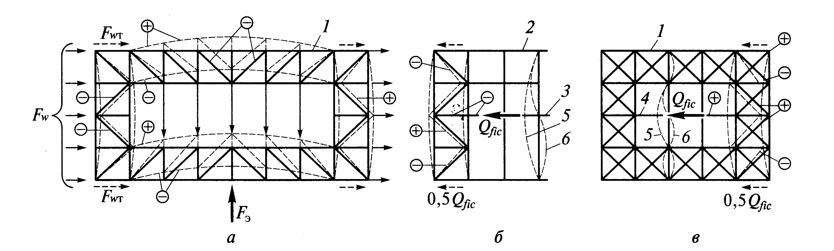
Rice. 9.19. Cover link work:
a - diagram of the operation of horizontal connections under the action of external loads; b and c "- the same, with conditional forces from the loss of stability of the truss belts; / - ties along the lower truss belts; 2 - the same, along the top; 3 - bracing of the ties; 4 - stretching of the ties; 5 - form of buckling or oscillation in the absence of spacers (stretch marks); 6 - the same, in the presence of spacers.
Horizontal forces from overhead cranes act in the transverse direction on one flat frame and two or three adjacent ones. Longitudinal connections ensure the joint operation of the system of flat frames, as a result of which the transverse deformations of the frame from the action of a concentrated force are significantly reduced (Fig. 9.19, a).
The rigidity of these links must be sufficient to involve adjacent frames in the work, and their width is assigned equal to the length of the first panel of the lower chord of the truss. Connections are usually installed on bolts. Welding of bonds increases their rigidity several times.
The panels of the lower chord of trusses adjacent to the supports, especially when the crossbar is rigidly connected to the column, can be compressed, in this case the longitudinal braces ensure the stability of the lower chord from the plane of the trusses. The transverse ties fix the longitudinal ones, and at the ends of the building they are also necessary for the perception of the wind load directed at the end of the building.
Fachwerk racks transmit the wind load F w to the nodes of the transverse horizontal end truss, the belts of which are the lower belts of the end and adjacent truss trusses (see Fig. 9.19, a). The support reactions of the end truss are perceived by vertical connections between the columns and are transferred to the foundation (see Fig. 9.19). In the plane of the lower chords, intermediate cross braces are also arranged, located in the same panels as the cross braces along the upper truss chords.
To avoid vibration of the lower chord of trusses due to the dynamic action of overhead cranes, it is necessary to limit the flexibility of the stretched part of the lower chord from the plane of the frame. In order to reduce the free length of the stretched part of the lower chord, in some cases it is necessary to provide braces that secure the lower chord in the lateral direction. These extensions perceive the conditional transverse force Q fic (Fig. 9.19, c).
In long buildings consisting of several temperature blocks, cross-braced trusses along the upper and lower chords are placed at each expansion joint (as at the ends), bearing in mind that each temperature block is a complete spatial complex.
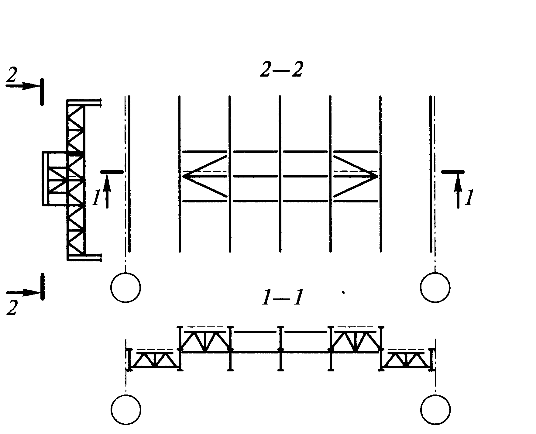
Vertical links between trusses are installed in the same axes in which horizontal cross braces are placed (see Fig. 9.20, c). Vertical connections are placed in the plane of the truss struts in the span and on the supports (when the trusses are supported at the level of the lower chord). In the span, one or two vertical connections are installed along the width of the span (in 12-15 m). Vertical ties give immutability to the spatial block, consisting of two truss trusses and horizontal cross ties along the upper and lower chords of the trusses. Rafter trusses have a slight lateral rigidity, therefore, during installation, they are fixed to a rigid spatial block with spacers.
In the absence of horizontal transverse ties along the upper chords, to ensure the rigidity of the spatial block and fix the upper chords from the plane, vertical ties are installed after 6 m (Fig. 9.20, e).
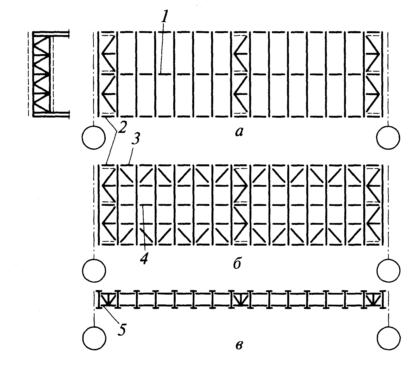
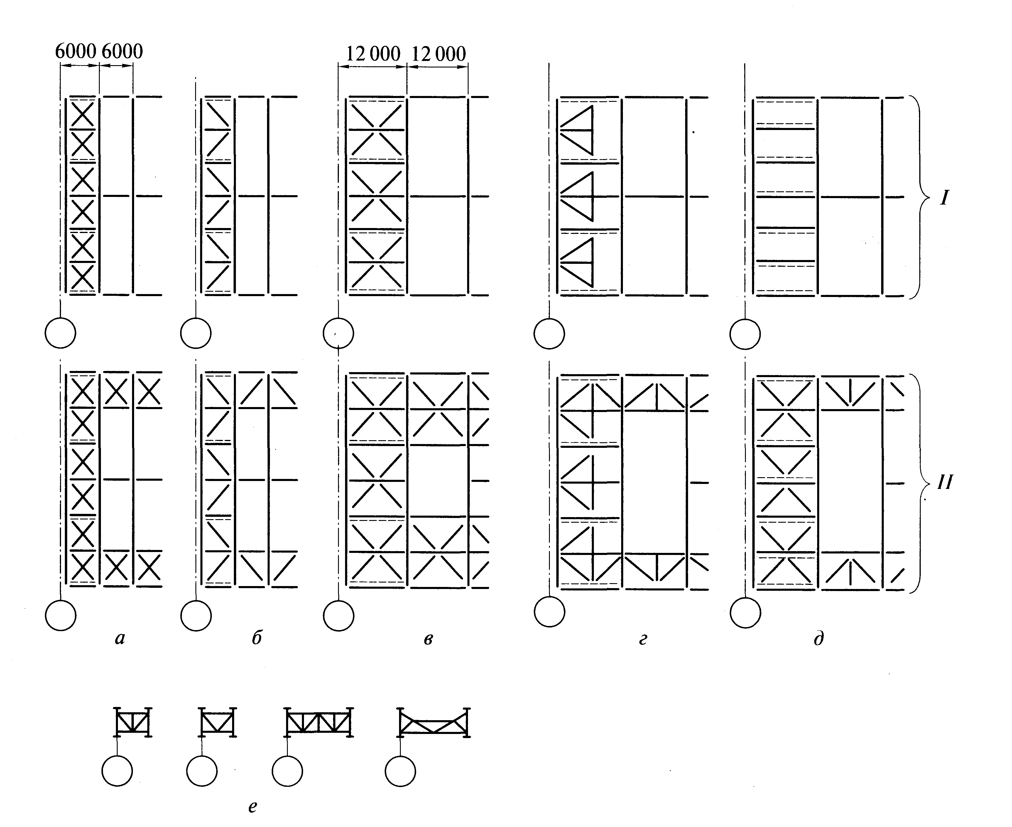
Rice. 9.20. Schemes of communication systems by coverage:
a - cross connections with a 6-meter step of frames; b - connections with a triangular lattice; c and d - the same, with a 12-meter frame step; e - a combination of horizontal ties along the lower chords of trusses with vertical ties; I, II - connections, respectively, on the upper and lower chords of farms
The sections of the connection elements depend on their design scheme and the pitch of the truss trusses. For horizontal connections with a truss pitch of 6 m, a cross or triangular lattice is used (Fig. 9.20, a, b). The braces of the cross lattice work only in tension, and the posts work in compression. Therefore, racks are usually designed from two corners of the cross section, and braces - from single corners. The elements of a triangular lattice can be both compressed and stretched, so they are usually designed from bent profiles. Triangular ties are somewhat heavier than cross ties, but their installation is easier.
With a truss pitch of 12 m, the diagonal elements of the connections, even in the cross lattice, are very heavy. Therefore, the system of connections is designed so that the longest element is no more than 12 m, diagonals support these elements (Fig. 9.20, c). On fig. 9.20, d shows the diagram of connections, where the diagonal elements fit into a square 6 m in size and rely on longitudinal elements 12 m long, which serve as belts of truss trusses. These elements have to be made of a composite section or from bent profiles.
Vertical connections between trusses and lanterns are best done in the form of separate transportable trusses, which is possible if their height is less than 3900 mm. Various schemes of vertical connections are shown in fig. 9.20, e.
On fig. 9.19 shows the signs of the forces arising in the elements of the pavement ties for a certain direction of the wind load, local horizontal forces and conditional transverse forces. Many link elements can be compressed or stretched. In this case, their section is selected according to the worst case - according to the flexibility for the compressed elements of the connections.
Spacers in the ridge of the upper chord of the trusses (element 3 in Fig. 9.19, b) ensure the stability of the upper chord from the plane of the trusses both during operation and during installation. In the latter case, they are attached to only one cross-link, their cross section is selected based on compression.
Metal carcass industrial building consists of a number of "flat" elements that are rigid and well accepting loads in their plane, but flexible in the perpendicular direction (frames, under-rafter and intermediate truss trusses, etc.). The main purpose of the connections is to unite flat elements into a spatial system capable of absorbing the loads acting on the building in any direction.
Secondly, the connections serve to ensure the stability of the compressed and compressed-bent rods of the upper chords of trusses, columns, etc. The danger of losing the stability of such elements is explained by the fact that the rods metal frame have large lengths and relatively small compact transverse dimensions. The braces release the compressed elements at intermediate points, reducing the calculated lengths of the elements in the direction of these releases.
There are the following main types of connections used in the metal frame of an industrial building
1) transverse connections between the upper chords of trusses (through beams of frames will be referred to as "trusses" in the future) (Fig. 1) 2) vertical connections between trusses (Fig. 9); 3) longitudinal and transverse ties located in the plane of the lower chords of trusses (Fig. II); 4) vertical connections between columns (Fig. 22). Consider the layout, purpose and design solutions of communication nodes using examples of buildings with different coatings.I. TRANSVERSAL RELATIONS BETWEEN THE UPPER BELTS OF TRUSSES
1.1. The upper chord of the truss, like any compressed rod, may lose stability if the force in it reaches a critical value. The loss of stability in this case will occur in one of two planes:
Fig.1. Cross connections between the upper chords of trusses, 2-2 each - vertical connections a) in the plane of the truss - the bar that has lost stability will remain in the plane of the truss. This means that when looking at the farm from above, the loss of stability will not be noticeable. As can be seen from Fig. 2, the calculated length when checking the stability of the upper chord "and the plane" of the truss corresponds to the distance - between the nodes, that is, the length of one panel;
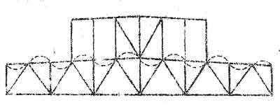
Fig.2. Estimated length of the upper chord in the truss plane, (dotted line)
b) the loss of stability of the upper belt with its exit from the plane of the farm should be shown only in plan. Let's assume that links are not set. Then the loss of stability will occur according to the scheme shown in Fig. 3a. The girders, which are usually attached to the upper chord of the truss articulated (using bolts), by themselves, without ties, will not prevent the buckling of the trusses, since after the loss of stability, the upper chords of the trusses will bulge, and the girders will freely move to a new position. At the same time, the distance between trusses (span of runs) will remain.
A different picture of stability will be observed if links are placed. Relations can be cross - with two diagonals (Fig. 3.6) and lightweight, triangular (Fig. 3, c), i.e. with one diagonal. Compressed diagonals, obviously, are switched off from work, having lost stability, and stretched ones will prevent the rectangles from being distorted, will not allow them to turn into parallelograms. Consequently, at the attachment points of the diagonals, the truss belt will retain its original position and its estimated length "out of the plane" will be equal to the "L-B" section (Fig. 3, c), i.e. two panels. The top chords of all trusses connected to these points by girders (or braces by lanterns) will have the same effective lengths as the chords of two trusses directly fixed with ties, i.e. sections A "-B", A ""-B"" have a calculated length equal to two panels. 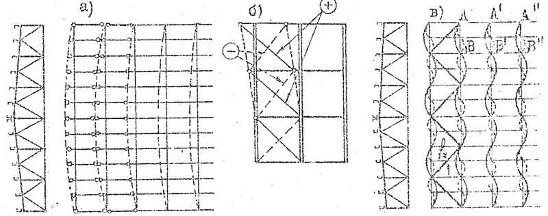
Fig.3. Loss of stability of the upper chords of trusses; a) in a cover without bonds; b) the scheme of tensioning and switching off the braces of the ties; c) ensuring the stability of believing belts with the help of rod connections
Let us pay attention to the error that can be made when determining the estimated length of the upper chord from the truss plane. In Fig. 3c, the run intersects the bonds diagonal at point "f". It seems that the run is attached to the diagonal of the ties, and the estimated length of the upper chord from the truss plane, it would seem, can be taken equal to the panel. However, this is not true: runs and connections are located at different levels, there is a gap between them "f" (Fig. 7)
1.2.
In buildings with a lantern (Fig. 4), the upper belt is not unfastened from the truss plane over a large area, because there are no runs under the lantern. If we consider that the structures of the wall fencing of the lantern, together with the run, fix the point "B", then the estimated length of the upper chord is from the plane "B~B". The introduction of a spacer in the middle of the lantern span reduces the estimated length from the truss plane (Fig. 4b) to three panels. 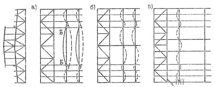
Fig.4. Estimated lengths of the upper belt under the lantern:
a) without spacers - 6 panels;
b) with one spacer - 3 panels;
c) with a truss spacing of 12 m, an intermediate communication belt PP is introduced
The upper belt of vertical ties (section 2) is used as a spacer, but paired corners or other profiles specially designed for this purpose can be used,
1.3.
AT recent times in order to save metal, it is customary to assign the functions of connections along the upper chords to the roofing, which, when securely attached to the trusses, can ensure the stability of the upper chords from the plane of the trusses.
So in non-purlin roofs with reinforced concrete flooring, the stability of the upper chords from the plane of the trusses is ensured by welding the embedded parts of the flooring to the upper chords. In this case, the estimated length of the upper belt from. truss plane can be taken equal to the length of one truss panel. 0 welding of the flooring to the chords of the trusses should be indicated in the note on the drawing.
During the erection of the building, these attachments of plates to chords must be controlled. In this case, it is required to draw up an act for hidden work. Profiled flooring can also act as ties along the upper chords if it is attached to the girders with dowels.
the best constructive solution when using profiled decking as ties, it will be one in which the girders are attached to the truss so that the top flange of the purlin is flush with the top flange of the truss belt. In this case, the flooring is shot with dowels on its four sides - to the girders and upper chords of the trusses. For the convenience of attaching the girders to the trusses, in this case, it is possible to use roof trusses not with a triangular lattice, but with descending braces (Fig. 5). 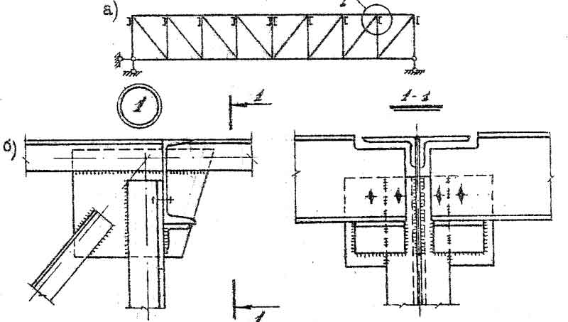
Fig.5. Use of profiled flooring as top chord ties:
a) roof truss with descending braces;
b) a variant of solving the support node of the run at the same level with the upper chord of the truss
With the economic advantages of replacing the ties with decking attached to the belts, the coatings are deprived of one important function performed by the ties. Connections along the upper chords, in addition to ensuring the stability of the trusses, are also fixers of the correct relative position of the trusses during installation. Therefore, when installing a coating without ties, it is recommended to provide for the use of temporary (removable) inventory ties, i.e. installation conductors.
If there are lanterns in the coatings, where the flooring serves as ties along the upper belt, under the lantern, to ensure the stability of the belt, ties are arranged in the form of diagonals with a truss step of 6 m or in the form of incomplete diagonals with a truss step of 12 m (Fig. 6). In this case, the estimated length of the upper chord of the trusses, when checking the stability from the plane, is taken equal to two panels. 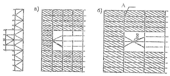
Fig.6. Ensuring the stability of the upper belts of trusses under the lanterns in the coatings, where it performs the functions of connections; flooring t a) truss spacing b m, b) truss spacing 12 m
1.4. In roofs with a truss spacing of 12 m and spans of 12 m, the truss truss is assumed to be 6 m wide. 6 m
1.5. The distance along the length of the building between the rod connections along the upper belt of the trusses should not exceed 144 m. Therefore, in long buildings, connections are placed not only in the extreme panels of the frame block, but also in the middle or thirds of the block length (Fig. I).
These requirements are explained by the fact that the stability of farms, located far away oh, t ties, cannot always be reliably ensured, because the girders or spacers that attach the trusses to the tie blocks allow a certain displacement in the nodes due to the difference in the diameters of the bolts and holes. With an increase in the number of nodes, i.e. with distant connections, this miscibility is added and increased, which reduces the reliability of the stability of farms located far from the connections.
The designs of some connection nodes made of angle and bend-welded profiles, and their attachment to trusses are shown in Fig. 7, 8.
So, the connections located in the plane of the upper truss chords have the following main purpose: when loading, the coatings prevent the loss of stability of these chords from the truss plane, that is, they reduce the estimated length of the upper chords when checking their stability from the truss plane.
2. VERTICAL LINKS BETWEEN FARMS
These connections are also called mounting, since their main purpose is to hold in design position placed on truss supports, to prevent single trusses from tipping over during installation from wind and accidental influences, because the center of gravity of the farm is above the level of the supports (Fig. 9, a).
Vertical connections in the form of a chain of struts and trusses are placed along the length of the building between the racks of the truss trusses. To save metal, tie trusses are interconnected by upper and lower struts (Fig. 10). Thus, the trusses of vertical ties are disks, and the spacer rods attached to them provide intermediate truss trusses or frame crossbars from tipping over (Fig. 9b). The lattice of braced trusses, as a rule, can be arbitrary (Fig. 9c) and is made from single corners or from rectangular bent-welded pipes. In pavements with a truss spacing of 12 m, with trussed girders or decking reinforced with trussed trusses, the upper chord of the vertical truss truss may look as shown in Fig. 9d.
Vertical connections along the width of the span are located on the supports (between the columns) and in the span between the racks. Trusses at least every 15 m, i.e. with a building span of 36 m, they will be located in the planes of two racks.
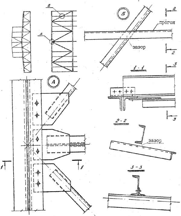
Fig.7. Attaching ties to the top truss chords
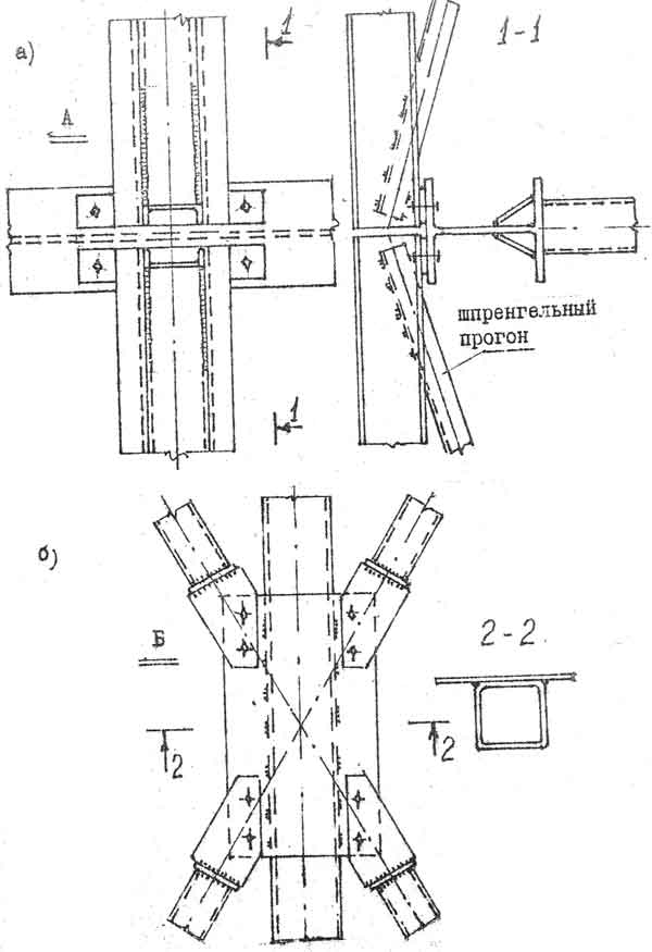
Fig.8. Nodes of coverage and connections at a truss spacing of 12 m (see Fig. 6);
a) Attaching connections made of closed profiles to trusses with belts from wide-shelf I-beams
b) Node B
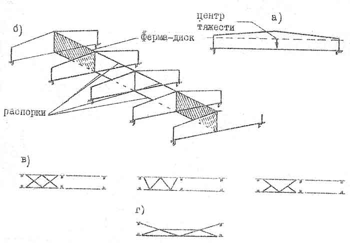
Fig.9. Vertical links between farms:
a) the position of the center of gravity,
b) trusses-disks and spacers,
c) truss lattice schemes,
d) connections in coverings with a truss step of 12 m and with trussed runs
Trusses - disks of vertical connections are placed in increments of 30-36 m along the length of the building. Racks of corner trusses, to which connections are attached in the upper and lower nodes, are made of a cross section (Fig. 10).
Ties can also be attached to vertical gussets specially provided for this purpose. As part of a block in large-block installation, vertical connections are necessary elements that ensure the immutability of the block. 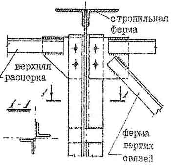
Fig.10. Knot for attaching the upper belt of the vertical truss truss to the rack of the truss truss. The bottom node is done in the same way.
LONGITUDINAL HORIZONTAL LINKS ALONG THE LOWER BELTS OF THE RIGEL
The contour of the ties located in the plane of the lower through crossbars can be divided into longitudinal and transverse ties (Fig. 11). The purpose of the longitudinal links is as follows:
3.1. Longitudinal connections perceive transverse horizontal crane actions, i.e. they perceive the eccentric application of the vertical pressure of the crane on the column, causing horizontal displacement of the frame, as well as the transverse braking of the crane applied to one frame (Fig. 12a) and transfers these effects to adjacent frames that are less loaded (Fig. 12b). Thus, the spatiality of the frame is ensured when it is working on local loads that cause horizontal displacements of the frame crossbar.
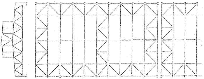
Fig.11. Connections on the lower chords of the crossbars of the frames
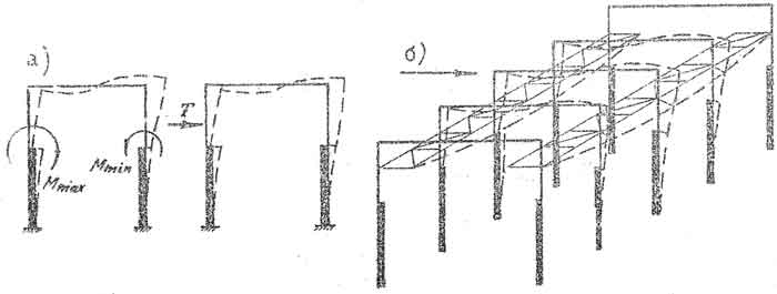
Fig.12. Scheme perceived by transverse horizontal loads by longitudinal braces along the lower chords:
a) mixing of frames from vertical eccentric application of the crane load and from braking;
b) transfer of transverse loads to connections
3.2. Note that the side load from the wind is transferred equally to all frames, causing the same mixing of them. In this case, there are no transverse forces between the frames, and therefore, in frames with a frame spacing of 6 m, longitudinal ties do not perceive wind loads,
With a column spacing of 12 m or more in frames with half-timbered (wall frame) racks, longitudinal ties work for this load; They are the upper horizontal supports of the half-timbered racks. Thus, in this case, the longitudinal ties transfer forces from wind loads from the half-timbered racks to adjacent frames (Fig. 13) and the ties are loaded with forces from the wind load along the step length of the frames. 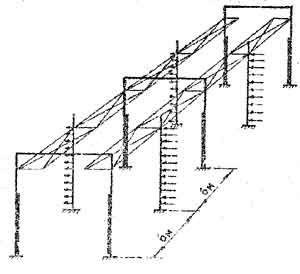
Fig.13. Transfer of wind load from half-timbered racks to longitudinal ties
3.3. In the extreme panels of the crossbar, due to the fact that the rigidly clamped crossbar on the support experiences bending moments of the opposite sign with respect to the sign of the moment in the span, compression of the lower chord is given (Fig. 14).
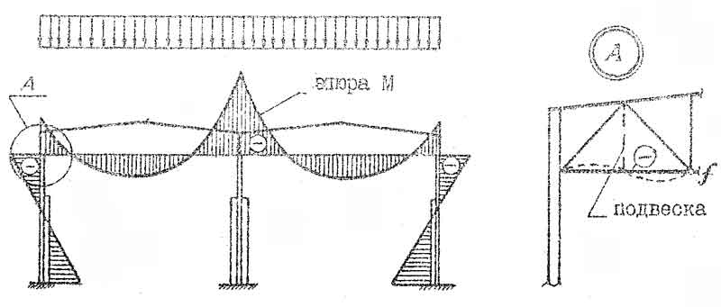
Fig.14. Compression in the lower chord of the crossbar near the supports
It is possible to fix the lower chord from the loss of stability from the plane of the crossbar here only with the help of longitudinal ties (point "f" Fig. 14). The stability of the lower chord in the plane of the crossbar is ensured either by the development of the moment of inertia of the chord section (in this panel it can be taken from two unequal angles made up of large shelves), or by introducing an additional suspension.
3.4. In multi-span buildings with heavy-duty cranes (7K, 8K), longitudinal connections in the form of horizontal trusses are placed from each other at a distance of no more than two spans (Fig. 15) 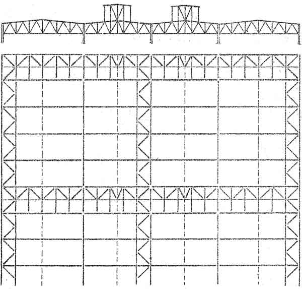
Fig.15. Connections along the lower chords of crossbars in a multi-span frame with heavy-duty cranes (7K, 8K)
In multi-span buildings with medium-duty cranes with a lifting capacity of up to 50 tons, with spans of not more than 36 m and with a height of up to 25 m, as well as with a frame pitch of 6 m, it is allowed not to make longitudinal connections along the lower chord. However, struts and tie rods, which ensure the stability of the lower chords from the plane of the trusses, must be placed in each span (Fig. 16). 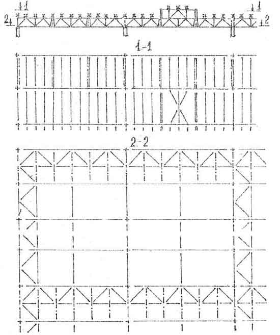
Fig.16. Connections on the lower chords in the frame with medium duty cranes (4K - 6K)
4. TRANSVERSAL LINKS IN THE PLANE OF THE LOWER CHORNS OF THE CAM
4.1. These connections serve to transfer forces from wind loads directed to the end of the building, from the racks of the end fachwerk to the vertical connections between the columns (Fig. 17) (pressure transfer is shown by arrows). 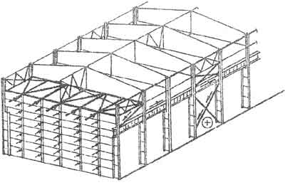
Fig.17. Scheme of transmission of wind loads from the end of the building in communication
4.2. Together with the longitudinal ties, they form a closed loop that increases the overall rigidity of the building frame.
Transverse braces, as a rule, are placed under the braces along the upper chords, creating with them spatial transverse blocks, to which intermediate trusses (crossbars) are attached with the help of girders, vertical braces and longitudinal braces.
Figures 18, 19 show the attachment points of horizontal ties made of angles and rectangular bent-welded pipes to truss chords. It should be noted that in heavy-duty frames of 7K, 8K cranes and at high crane loads, ties are attached to trusses by welding (i.e., bolted assemblies must be welded) or using high-strength bolts. 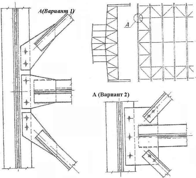
Fig.18. Designs of corner ties along the lower chords
5. VERTICAL LINKS BETWEEN COLUMNS
Distinguish between the upper tier of vertical connections between the columns (connections located above the crane beams) and the lower one below the beams (Fig. 20).
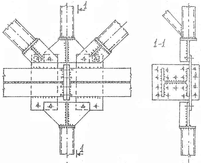
Fig.19. Knot of connections along the lower belt from rectangular bent-welded profiles
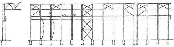
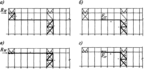
Fig.20. Scheme of vertical connections between columns
5.1. The connections of the upper tier have the following purpose:
a) the forces from the wind directed to the end of the building are transferred to the connections of the upper tier from the end cross-braces located in the plane of the lower chords, and then, along the stretched struts, these forces are transferred to the crane beams",
b) connections of the upper tier provide - the stability of the columns "from the plane" of the frames. Thus, the calculated length of the over-crane part of the column (Fig. 20, dotted line) from the plane of the frame is equal to the height of this part of the column;
c) together with the lower tier of connections during installation, they keep the columns fastened with anchors from tipping over.
5.2. Vertical connections of the lower tier
The following functions are assigned to the connections of the lower tier:
a) transfer wind forces from the connections of the upper tier and from the longitudinal braking of cranes (Fig. 20);
b) ensure the stability of the crane part of the colony from the plane of the frame;
c) serve as mounting connections when installing columns. In high-rise buildings, the connections of the lower tier have an additional spacer between the columns - (Fig. 21,
a). Its purpose is to reduce the estimated length of the crane part of the column from the plane of the frame. This layout technique is resorted to when, during the calculation, I check the stability of the column "from the plane" does not give satisfactory results due to the high flexibility of the column (from the plane of the frame.).
Schemes of vertical connections can be different depending on the pitch of the columns, on the need to use an opening between the columns, etc. (Fig. 21b). 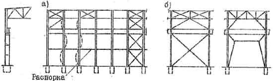
Fig.21. Schemes of vertical connections of the lower tier:
a) additional spacer to reduce the estimated length of the column from the plane of the frame;
b) options for connections between columns
It is not necessary to attach the ties of the lower tier to the crane beams in the span, since when the crane moves, compression of the braces of the ties may occur, and, consequently, they can be turned off. Upper tier braces can be attached to the brake beams with oval bolts in a vertical direction. 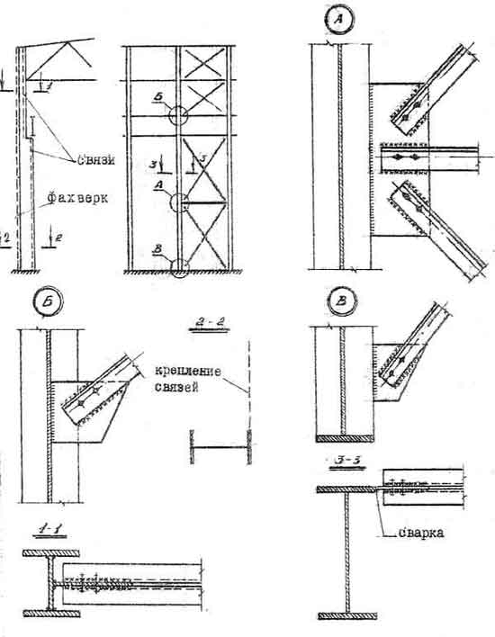
Fig.22. Structures of vertical connections between columns with a column spacing of 6 m
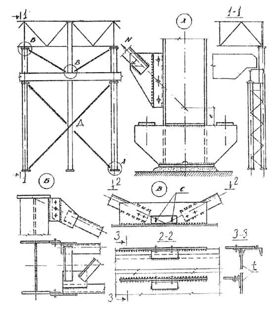
Rice. 23. Vertical connections between columns with a column spacing of 12 m: C - oval holes in node B, allowing deflections of the crane beam without loading the connections of the upper tier; t - brake beam
In the vertical plane, the upper tier of ties is usually located along the axis of the over-crane part of the column, and the lower ties should be double and should be located in the planes of both the outer and inner branches of the crane part of the column (Fig. 22). If there is a fachwerk, then the connections are established in the plane of the fachwerk and are joined to the fachwerk post in the middle node. Along the length of the building, the connections of the lower tier are placed in the middle of the temperature block (Fig. 22), but not in the cream case at the ends. Placing the connections in the middle of the building ensures free deformation of the longitudinal elements with temperature fluctuations (elongation or shortening of crane beams, longitudinal connections, etc. .). 
Fig.24. Middle knot of vertical connections (see fig. 23):
Г - fastening of connections and fachwerk rack f on assembly welding, D - on high-strength bolts, Q - stiffeners, 4-4 - calculated section of the gusset. Bolts are calculated for the axial force in the diagonal of the ties and the moment from the eccentricity "a"
6. CALCULATION OF RELATIONSHIPS
In most types of connections, it is difficult to accurately determine the magnitude of the efforts that will be perceived by them. Therefore, the sections of the elements of connections, as a rule, are selected according to the ultimate flexibility. For elements that are known in advance that they will experience compression, it is recommended to take an ultimate flexibility of 200.
According to the known forces, vertical ties between columns, as well as transverse ties along the lower chord of the crossbar and longitudinal horizontal ties (in the case of taking into account the spatial work of the frame) are calculated.
- SNiP II-23-81*. Steel structures, - M., Stroyizdat, 1988, - 96 p.
- Belenya E.I. and others. Metal constructions.- M., Stroyizdat, 1989.- P.272-279.
- SNiP 2.01.07.-85. Loads and influences. - M., Stroyizdat, 1989.
- Central Research Institute Projectstalkonstruktsiya im. Melnikova, Typical building construction, products and components. Series 2.440-2, Structural units industrial buildings industrial enterprises: Issue 4. Knots of brake structures and vertical links. KM drawings. Moscow, 1989. 49 p.
- Benefit on the design of steel structures (to SNiP 23-81 *) - M., Central Institute for Standard Design, 1989 -148s.
