Installation of ties in a metal frame. Kirsanov N.M. Lecture text
The metal frame consists of many load-bearing elements (truss, frame, columns, beams, crossbars), which must be "connected" to each other to maintain the stability of compressed elements, rigidity and geometric invariability of the structure of the entire building. To connect structural elements frame serve metal ties... They take up the main longitudinal and lateral loads and transfer them to the foundation. Metal braces also distribute loads evenly between trusses and frame frames to maintain overall stability. Their important purpose is to resist horizontal loads, i.e. wind loads.
Saratov Reservoir Plant produces ties from hot-rolled section angles, bent angles, bent shaped pipes, hot-rolled profile pipes, round pipes, hot-rolled and bent channels and I-beams. The total weight of the metal used should be approximately 10% of the total weight of the building's steel structure.
The main elements that connect the ties are trusses and columns.
Column metal ties
Column connections ensure the lateral stability of the metal structure of the building and its spatial immutability. The connections of the columns and pillars are vertical metal structures and structurally are spacers or discs that form a system of longitudinal frames. The purpose of hard drives is to secure columns to the foundation of a building. Spacers connect the columns horizontally. The spacers are longitudinal beam elements such as floor slabs, crane beams.
Inside the connections of the columns, there are connections of the upper tier and connections of the lower tier of columns... The ties of the upper tier are located above the crane beams, the ties of the lower tier are, respectively, below the beams. The main functional purposes of the loads of the two tiers are the ability to transfer the wind load to the end of the building from the upper tier through the cross-braces of the lower tier to the crane beams. The upper and lower braces also help keep the structure from tipping over during installation. The connections of the lower tier also transfer the loads from the longitudinal braking of the cranes to the crane beams, which ensures the stability of the crane part of the columns. Basically, in the process of erecting the metal structures of the building, the connections of the lower tiers are used.
Diagram of vertical connections between columns
Metal truss ties
To impart spatial rigidity to the structure of a building or structure, metal trusses are also connected by ties. A truss link is a spatial block with adjacent trusses attached to it. Adjacent trusses on the upper and lower chords are connected horizontal truss links, and along the lattice posts - vertical truss links.
Horizontal truss ties along the lower and upper chords
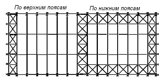
Horizontal ties of trusses are also longitudinal and transverse.
The lower chords of the trusses are connected by transverse and longitudinal horizontal ties: the former fix the vertical ties and stretch marks, thereby reducing the vibration level of the chords of the trusses; the latter serve as supports for the upper ends of the longitudinal half-timbered posts and evenly distribute the loads on adjacent frames.
The upper chords of the trusses are connected by horizontal cross-braces in the form of struts or purlins to maintain the projected position of the trusses. Cross ties unite the upper chords of the truss into a single system and become a "closing face". The spacers just prevent the trusses from shifting, and the horizontal transverse trusses / ties prevent the spacers from shifting.
The vertical ties of trusses are necessary in the process of erecting a building or structure. They are often called assembly connections. Vertical braces help to maintain the stability of trusses due to the displacement of their center of gravity above the supports. Together with intermediate trusses, they form a spatially rigid block at the ends of the building. Structurally, the vertical trusses of the trusses are discs consisting of spacers and trusses, which are located between the racks of the truss trusses along the entire length of the building.
Vertical links of columns and trusses

Steel frame metal tie structures
By design, metal bonds are also:
cross-links, when link elements intersect and connect in the middle
corner braces, which are located in several parts in a row; used mainly for the construction of low-span frames
portal links for U-shaped frames (with openings) have a large surface area
The main type of connection of metal ties is bolted, since this type of fastening is the most effective, reliable and convenient during the installation process.
Specialists of the Saratov Reservoir Plant will design and manufacture metal ties from any profile in accordance with the mechanical requirements for the physical and chemical properties of the material, depending on the technical and operational conditions.
The reliability, stability and rigidity of the metal frame of your building or structure largely depends on the high-quality manufacturing of metal ties.
How to order the production of metal ties at the Saratov Reservoir Plant?
To calculate the cost of metal structures of our production, you can:
- contact us by phone 8-800-555-9480
- write on email technical requirements for metal structures
- use the form "", indicate contact information, and our specialist will contact you
The Plant's specialists offer comprehensive services:
- engineering surveys at the operation site
- design of oil and gas facilities
- production and installation of various metal structures
The stability of the columns in the longitudinal direction is ensured by vertical ties between the columns. The braces are placed in the middle of the building or temperature compartment in order to reduce the thermal deformation of the longitudinal elements less.
Rice. 6.1. Vertical ties between columns.
Vertical ties between the columns are placed along all rows of the building. The simplest connection scheme is cross. The rational angle of inclination of the bonds is 35-55º.
Vertical ties between the columns perceive the forces from the wind acting on the end of the building and the longitudinal braking of the cranes. Cross-link elements work in tension.
Coverage connections.
The connections on the structures of the building covering are set to ensure the spatial rigidity of the frame, the stability of the covering as a whole and its elements separately. They can be horizontal in the planes of the upper or lower chords. In another case, they can be vertical between the truss trusses, while the links along the upper chords of the trusses consist of transverse truss trusses and longitudinal elements between them.
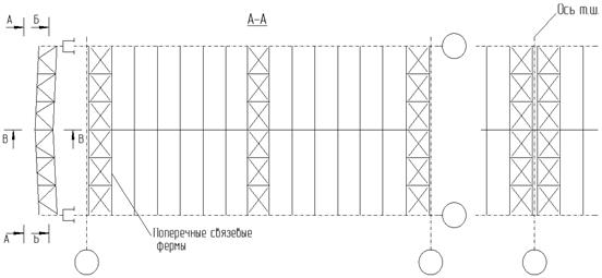
Fig 6.2. Horizontal with cover knitting .
Coating ties are placed to ensure the stability of the compressed rods of the upper chord during buckling from the plane of the trusses. It is most advisable to locate such connections at the ends of the shop. With a long building length, additional intermediate transverse trusses are advisable, the distance between which should be no more than 60 m.
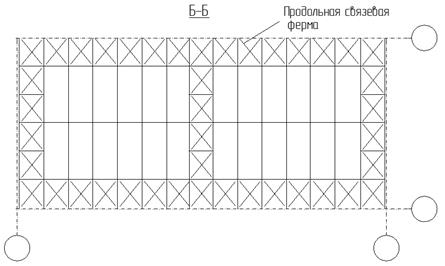
Fig 6.3. ... Vertical with cover knitting .
Horizontal ties along the lower belts of trusses are located both across the shop (cross ties) and along it (longitudinal ties). The cross braces located at the ends of the workshop are used as wind trusses. The belts of the wind farm are the belts of the truss trusses.
Horizontal longitudinal ties along the lower chords of trusses have as their main purpose the involvement of adjacent frames in the spatial work under the action of crane loads, thereby reducing frame deformations and increasing the lateral rigidity of the workshop.
For braced trusses, as a rule, a cross lattice is taken, considering that when loads are applied from one side, only the system of stretched braces works, and the other part of the braces (compressed) is turned off. This assumption is valid if the braces are flexible (λ> 200).
Vertical ties between trusses are usually installed at the truss supports (between the columns) and in the middle of the span, placing them along the length of the workshop in rigid panels, i.e. where cross-links are located along the truss belts.
The main purpose of vertical ties is to bring into a rigid unchanged state of a spatial structure, consisting of two truss trusses and cross ties along the upper and lower belts of the trusses. The design of vertical braces is adopted in the form of a cross from single corners with a mandatory horizontal closing element or in the form of a truss with a triangular lattice.
Due to the insignificance of the forces acting in the elements of the connections of the coating, when designing their fasteners, a slight deviation from centering can be allowed.
Conclusion.
For the considered example (see design assignment), a calculation was performed transverse frame determined by its General characteristics... Found all cross frame sizes , characteristics required for further static analysis.
Permanent and temporary loads of the transverse frame are calculated.
The supporting structure of the frame covering is a truss with parallel belts, span of 36 m, cross-section - rods from paired corners. For permanent and temporary snow loads, a static calculation was carried out and the calculated compressive and tensile forces of all truss rods were determined. The cross-sectional areas of the truss rods correspond to the design forces, which is confirmed by strength checks. The lengths of the welded seams for attaching the truss rods were found, and the design of the support unit was proposed.
For the selection of sections of the frame elements, the calculation of its mating nodes and other parts, a static calculation was carried out (the "PAMA" program) and the maximum forces (bending moments, longitudinal and transverse forces) were determined. The methodology for assessing the maximum efforts under the influence of constant and temporary loads is considered. The maximum forces in all required frame sections have been determined.
To substantiate the cross-sectional area of the column, the calculated lengths of its upper and lower parts were determined. The bearing element of the upper part of the column is a rolled I-beam 70B2. The calculation of the stability of the upper part of the column as an eccentrically compressed bar, in the plane and from the plane of eccentricity. It is shown that the stability of the upper part of the column is ensured.
The through bottom part of the column consists of a composite channel (outer branch) and an I-beam (crane girder), connected to each other by a lattice of rolling equal-flange angles. The design forces are determined, the section of the outer branch is selected. The calculation of the stability of the outer branch as an eccentrically compressed rod, in the plane and from the plane of eccentricity. It is shown that the stability of the outer branch is ensured.
A cross-sectional area was selected for the crane branch, a welded composite I-beam is used as a rod, its main characteristics are calculated. The stability of the crane branch in the plane and out of the plane of the frame was checked. It is shown that the stability of the crane leg is provided.
It is shown that the stability of the lower part of the column as a single compressed-bent bar in the plane of the moment action is provided.
Calculations of the supporting part of the column are carried out. For the crane runway, the dimensions of the base plate, the thickness and height of the traverse are determined. It is shown that the strength of the crosshead along the normal sections and for the shear at the support is sufficient. The lengths of the seams during welding are determined.
The design of the ties installed in the roof depends on the layout and material of the frame, the type of coating, the height of the building, the type of crane, its lifting capacity and operating mode.
Vertical ties between the supports of reinforced concrete trusses or roof beams are installed only in buildings with a flat roof, and in buildings without sub-rafter structures, ties are placed in each row of columns, and with such structures - only in the extreme rows of columns at a step of 6 m.
Vertical ties between the supports of trusses or beams are placed no more often than one step later. Their number with a temperature block length of 60-72 At for each row of columns can be no more than 5 with a step of 6 m and no more than 3 with a step of 12 m. 69, and four such connections are shown.
In the presence of vertical ties between the supports of trusses or roof beams or ties between columns (in buildings without cranes) along the top of the columns, st.
In buildings with a column pitch in the middle and outer rows of 12 m, horizontal trusses are provided at the ends - two in each span per temperature block. These trusses are placed at the level of the lower chord of the trusses (Fig. 69, c). In buildings with truss structures in the middle rows of columns, horizontal spacers are arranged in the amount of 2-4 per row of columns of the temperature block (Fig. 69, b).
Rice. 69. Connections in coatings with reinforced concrete trusses
In buildings with heavy-duty bridge cranes or in the presence of equipment that causes vibrations of structures, spacers (ties) and vertical ties are installed along the lower chord of trusses or beams in the middle of each span in the two extreme steps of the temperature block. The role of horizontal ties along the upper chord of trusses or beams is performed by large-panel slabs cover.
In spans with lanterns, to ensure the stability of the upper belt of the trusses, spacers (straps) are installed along the ridge of the trusses and horizontal ties along their upper belt within the width of the lantern in the extreme (or second) steps of the temperature block.
In coatings with girders at the extreme steps of the temperature blocks along their entire width, horizontal connections of the cross pattern are arranged under the girders.
Vertical and horizontal ties are made in most cases from corners and attached to reinforced concrete structures using kerchiefs (Fig. 69, d, e). The rods are made of round steel and the compression struts are made of reinforced concrete.
Coating linkage system in buildings with steel frame consists of horizontal ties in the plane of the lower and upper chords of truss trusses and vertical ties between the trusses.
Horizontal ties along the lower belts of roof trusses are placed both across the building (transverse horizontal) and along it (longitudinal horizontal). Transverse horizontal ties along the lower chords are installed at the ends and at the expansion joints of the building. With temperature blocks 120-150 m long and with heavy-duty cranes, intermediate trusses are also provided every 60 m.
Longitudinal horizontal ties are placed on the extreme panels of the lower chords of the truss trusses and are arranged in buildings with cranes Q> 10T and in buildings with truss trusses.
In single-span buildings, such ties are located along both rows of columns, and in multi-span buildings - along the outer rows of columns and through a row along the middle rows (with cranes with a lifting capacity of up to 50 7) or more often (with a crane with a lifting capacity of more than 50 T).
Along the middle rows of columns with the same height of adjacent spans, longitudinal ties are recommended to be placed on one side of the columns, and in dreams of heights - on both sides of the row of columns.
The lateral rigidity of the lower chords of the trusses, located in the interval between the two transverse truss trusses, rests with special stretch marks from the corners, fixed to the nodes of the truss trusses. The breakdown diagram of transverse and longitudinal ties along the lower belts of trusses is shown in Fig. 70, a.
Horizontal cross-braces along the upper chords of the trusses ensure the stability of the upper chords of the trusses from their plane, and they are placed in covers with purlins. In panel coverings, these connections are provided only at the ends of the building and at the expansion joints. In the intervals between the transverse trusses, the lateral stability of the upper belts of the trusses is ensured by girders, and in the areas under the lanterns - by stretch marks from the corners. It is recommended to combine cross ties along the upper and lower chords of trusses in plan.

Rice. 70. Ties in coatings for steel trusses
In the presence of trusses in single-span roofs without purlins and in multi-span roofs located at the same level, longitudinal horizontal ties are provided in the plane of the upper chords in one of the outer panels of the trusses. In the case of a difference in the heights of adjacent spans, one longitudinal system is provided at each level.
The vertical ties of the covering are located in the planes of the support posts of the rafter trusses, in the plane of the ridge posts, for trusses with a span of up to 30 m, as well as in the plane of the pillars located under the attachment point of the outer legs of the lantern for trusses with a span of more than 30 m.Vertical ties are made in the form of trusses with parallel belts, having a height equal to the height of the racks, to which the ties are attached.
Connections along purlins in the form of stiffening trusses, struts and ties provide design position purlins, increase stability and facilitate the operation of purlins on the sloping component of vertical loads and absorb wind forces.
All types of truss trusses are made of corners with a cross lattice, spacers are also made of corners, and ties are made of round steel. Ties are fastened on black bolts, in buildings with heavy-duty and heavy-duty cranes, as well as in the case of significant efforts in the elements of ties - on assembly welding and less often - on rivets or clean bolts. Some details of fastening ties are shown in Fig. 70, b - g.
Vertical braces, as the most economical structures, in most cases reliably provide the rigidity of buildings with a steel frame.1.1. From a static point of view, they are bent cantilever beams clamped in the ground.
1.2. In narrow vertical ties, significant forces arise, and the rods themselves undergo large deformations along the length, which contributes to large deformations of the facade with a small column pitch.
1.4. The stiffness of narrow wind braces can be increased by combining them with the outer columns.
1.5. The same effect is exerted by a high horizontal beam (for example, in the technical floor of a high-rise building). It reduces the distortion of the upper transom of the half-timbered timber and the deviation of the building from the vertical.
The location of the vertical connections in the plan
In terms of vertical ties are required in two directions. Solid or lattice vertical braces inside the building impede the free use of premises; they are placed inside walls or partitions with a small number of openings.2.1. Vertical braces surround the staircase.
2.2. Building with three cross braces and one longitudinal brace. With a narrow core of stiffness in tall buildings ensuring rigidity is advisable according to schemes 1 .4 or 1.5.
2.3. Cross braces in windowless end walls are economical and efficient; longitudinal connection in one span between two inner columns.
2.4. Vertical braces are located in the outer walls. Thus, the type of building is directly dependent on the structure.
2.5. High building with a square plan and vertical ties between the four inner columns. The required rigidity in both directions is provided by using schemes 1.4 or 1.5.
2.6. In high-rise buildings with a square or near-square plan, the arrangement of the connections in the outer walls allows for particularly cost-effective building structures.
Positioning the links in the wireframe
3.1. All links are located one above the other.3.2. The vertical ties of individual floors do not lie one above the other, but are mutually displaced. Interfloor ceilings transfer horizontal forces from one vertical connection to another. The rigidity of each floor must be ensured in accordance with the calculation.
3.3. Lattice braces along the outer walls, participating in the transfer of vertical and horizontal loads.
Influence of vertical ties on the base
Columns of a building, as a rule, are at the same time elements of vertical ties. They experience forces from the wind and from the load on the floors. The wind load causes tensile or compressive forces in the columns. The forces in the columns from vertical loads are always compressive. For the stability of the building, it is necessary that compression forces prevail in the base of all foundations, however, in some cases, the tensile forces in the columns may be greater than the compressive forces. In this case, the weight of the foundations is taken into account as ballast.4.1. Corner columns perceive insignificant vertical loads, however, with a large spacing of ties, the forces arising in these columns from the wind are also insignificant, and therefore artificial loading of corner foundations is usually not required.
4.2. Internal columns take up large vertical loads, and because of the small width of the wind links and large forces from the wind.
4.3. Wind forces are the same as in diagram 4.2, but are balanced by small vertical loads due to the outer columns. In this case, loading of the foundations is necessary.
4.4. It is not necessary to load the foundations if the outer columns stand on a high basement wall, which is able to balance the tensile forces from the wind.
5. The stiffness of buildings in the transverse direction is ensured by means of lattice ties in the windowless end walls. The connections are hidden between outside wall and an internal fire-resistant lining. In the longitudinal direction, the building has vertical ties in the corridor wall, but they are not located one above the other, but are displaced in different floors. - Faculty of Veterinary Medicine in West Berlin. Architects: Dr. Luckhardt and Wandelt.
6. The stiffness of the frame is provided in the transverse direction by lattice discs that pass through both buildings of the building, going out in the gaps between buildings. The stiffness of the building in the longitudinal direction is provided by the bonds between the inner rows of columns. - High-rise building "Phoenix-Rainror" in Dusseldorf. Architects: Hentrich and Petchnig.
7. A three-span building with a column pitch in the transverse direction 7; 3.5; 7 m. There are narrow transverse links between four inner columns located in pairs, and a longitudinal link between two inner columns of the same row. Due to the small width of the cross-links, the calculated horizontal deformations from the action of the wind are very large. Therefore, in the second and fifth floors, tension braces to the outer columns are installed in four tie planes.
The tension rods are made in the form of steel strips placed on the edge. They are pre-stressed (the stress is controlled by strain gauges) so that under the action of the wind, the stress of the stretched brace in one direction doubles, and in the other direction it becomes almost zero. - The building of the head office of the company "Bevag" in West Berlin. Architect prof. Baumgarten.
8. The building has only external columns. The beams cover a span of 12.5 m, the pitch of the outer columns is 7.5 m. In the high part, the wind ties are located across the entire width of the building between the outer columns. The outer columns take up heavy loads, which compensates for tensile forces from the wind. The pediment of the high part of the building protrudes 2.5 m in front of the columns. The connections located in the end walls continue within the first hidden floor between the columns with the transfer of horizontal forces from the upper connection to the lower one along the horizontal connection in the lower interfloor overlap. To transfer the total support forces, a solid steel sheet beam is used to the floor height, located in the technical floor between the penultimate and last columns. This beam forms a cantilever up to the gable wall. - The high-rise building of the television center in West Berlin. Architect Tepec. Designer Dipl. Ing. Treptov.
9. Ensuring the rigidity of the building with the help of external ties that transfer part of the vertical loads to the intermediate columns. Details - Administrative building firm "Alcoa" in San Francisco. Architects: Skidmore, Owings, Merrill.
10. Ensuring the stiffness of the building in the transverse direction: in the lower part thanks to the heavy reinforced concrete wall, in the upper part using the ties located in front of the facade, which are shifted in a checkerboard pattern. Each floor has six connections. Tie rods are made of tubular profiles. Stiffness in the longitudinal direction is provided by the installation of half-timbered ties in the middle rows of the columns. Details - Residential high-rise building on rue Krulebarb in Paris. Architects: Albert-Boileau and Labourdet.
Vertical ties along the columns are designed, as a rule, from corners - single and double, connected by a T-bar or a cross. The sections of the corners are assigned depending on the nature of the work of this element, the magnitude of the force acting in it, as well as on the length of the element. In this case, the working elements of the links are selected according to the efforts acting in them and according to the maximum flexibility, the non-working elements - only according to the maximum flexibility.
Vertical braces are recommended to be located in several vertical planes between two trusses under each transverse truss of the upper chord.
Due to the ease of installation, vertical ties are recommended to be carried out in the form of trusses with parallel chords. The height of these trusses is determined by the height of the rack of the rafter trusses to which they are attached.
Underfloor prestressed structures. Vertical braces are usually placed between columns to provide longitudinal rigidity to the frame. They are fixed in longitudinal rows and in the middle of the temperature block.
Vertical ties are made in the form of paired rolling corners connected by sections of channels; the ends of the ties in the form of kerchiefs are welded to the embedded sheets of the corresponding columns of the frame.
Vertical ties between the supporting structures of the coating. Vertical braces are installed between the columns and in the roof.
Vertical ties between the columns provide longitudinal rigidity of the frame columns. They are arranged in each longitudinal row, in the middle of the temperature block, limited by expansion joints or the end of the building.
Connection diagrams. Vertical ties, ensuring the correct location of each truss in the vertical plane, are usually placed in the planes of the truss support racks, and sometimes in the middle of the span.
The vertical braces between the trusses ensure the stability of the trusses during installation, and in the installed roof structures, they increase the overall rigidity of the block, consisting of two trusses and cross braces along the upper and lower chords. Vertical ties are usually located at the ends and in the middle of the span of the truss at a distance of 9 - 12 m from one another along the length of the truss. For truss spans up to 24m, it is enough to put one tie in the middle, and for large spans - two or three ties. Along the length of the workshop, vertical ties are placed after three or four steps of the truss trusses, necessarily combining them with the cross ties in the planes of the upper and lower belts of the trusses.
Vertical braces are usually made of steel corners (Fig. 7 - 7 e) are installed in the middle of the temperature compartment and attached to the columns at the junction of crane beams, struts and other horizontal frame elements. The cross-section of vertical ties is determined by calculating the forces arising in the ties from the wind acting on the end walls of the building, and from the braking forces of overhead cranes.
Vertical ties between trusses and lanterns are best done in the form of separate transportable trusses, which is possible if their height is less than 3900 mm. Possible schemes of vertical connections are shown in races.
Section of the columns of the stacks. change the continuous reef flooring. Vertical braces according to the diagonal scheme take T-sections from two unequal corners, and in the cross scheme, the stretched braces of the braces - from single isosceles corners.
Vertical braces between columns are located in the middle of the temperature block in each row of columns.
Vertical ties between steel columns are placed along each longitudinal row of columns and are divided into main and upper ones.
Vertical ties are made in the form of trusses with parallel belts having a height equal to the height of the racks to which the ties are attached.
Vertical braces from rolled sections are installed between the columns in each longitudinal row and in the middle of the temperature block.
Vertical braces in the coating for the perception of wind forces on the end of the building and from the braking of the cranes are performed in the form of diaphragms, reinforced concrete bezel-less trusses or a cross-shaped lattice made of steel corners. Such connections between the bearing structures of the coating are arranged in the extreme steps of the temperature block.
Vertical braces, spacers, braces and braces can be designed from round electric-welded pipes, closed bent-welded sections, bent and hot-rolled sections. An assortment of ties made of round electric-welded pipes was adopted as the main option.
Vertical ties in the coverage plane and in buildings with spans of 18 and 24 m are installed at the ends of the temperature block in the middle of the span, and in buildings with spans of 30 and 36 m - at distances of 3 and 6 m from the middle of the span, respectively.
Vertical braces on the posts are located in the same steps as horizontal trusses.
Vertical ties along the columns are established in the same way as in one-story buildings with roof trusses.
Calculation diagram of cross ties.
Vertical ties are designed of two types: basic - located along the entire height of the columns from the upper end to the foundations; upper - located within the upper sections of the columns to the top of the crane beams.
Vertical braces below the level of the crane beams with two-branch main columns are recommended to be placed in the plane of each of the column branches; if there is a half-timbered timber in the plane of the outer branch of the columns, it is allowed to install braces on the lower section of the main column only in the plane of the crane branch of the column.
Connection diagrams for crane trusses. Vertical ties along the beams are provided for the block installation of crane structures or in the case when it is necessary to ensure the spatial operation of crane structures.
Nodes of fastening of elements of connections from pipes (arrangement of nodes on,. Vertical connections should be made from profiles of the same type, which is adopted for horizontal connections.
Vertical braces are located at the locations of the transverse trusses along the lower belts of the truss trusses at a distance of 6 - 9 m from each other.
Outline diagrams of buildings with a coating Module. | Columns of buildings with support cranes | Craneless column base | Crane column base. Vertical ties along columns for craneless buildings - single-plane, cross-type; in buildings with cranes - U-shaped. Buildings with coatings Kislo-Iodsk and Module do not have vertical connections along the columns.
Arrangement of steel embedded parts in a precast concrete column. Vertical ties located along the line of the building columns create rigidity and geometric invariability of the frame columns in the longitudinal direction. Their device is provided for each longitudinal row, in the middle of the temperature block. The temperature block is the section along the length of the building between the expansion joints or between the expansion joint and the outer wall of the building closest to it.
Vertical coverage ties between trusses. Vertical connections between the supporting structures of the coating are arranged in the extreme spans of the temperature compartment, limited by expansion joints or the end of the building. These connections are designed to perceive the braking forces of cranes, as well as wind effects on the end of the building.
Prefab Mates reinforced concrete structures... Vertical ties are arranged in the plane of each longitudinal row of columns, between the extreme columns at the ends and at the expansion joints.
It is advisable to place vertical ties along the columns in the middle of the temperature compartment; with the length of the temperature compartment exceeding the permissible SNiP, two panels of connections are installed with the distance between the axes of the panels not exceeding the permissible ones.
Vertical ties are installed between columns 9-11 and 13-15 along all rows. Along the middle rows (in the intervals between the frames), they are supported: along the B - D axis - on the lattice truss trusses, and along the C row - with the help of suspensions.
Vertical ties along the beams are provided for the block installation of crane structures or in the case when it is necessary to ensure the spatial operation of crane structures.
Vertical ties are installed at the locations of horizontal cross ties.
Steel consumption for the frame of a single-span building with frame structures of the Alma-Ata type. Vertical braces along the columns are designed from single corners and installed in one panel along the length of the building.
The limits of the control function. Vertical links connect hierarchical levels in an organization and its parts.
Vertical connections include cooperation between suppliers and manufacturers, as well as the connection of distribution channels between organizations, or these are the connections of organizations located at different levels of the technological chain of a production process.
Vertical ties between the columns are placed along all rows of the columns of the building; they should be placed between the same axes.
Vertical braces, together with transverse braced trusses along the upper and lower chords, provide the creation of rigid spatial blocks at the ends of the building. Intermediate trusses are tied to these blocks with spacers and braces.
Vertical ties between trusses and lanterns are best done in the form of separate transportable trusses, which is possible if their height is less than 3900 mm.
Vertical braces are designed in the form of cantilever trusses, clamped into the foundation. In a frame system, the forces from wind loads are transmitted to the foundation more evenly.
Vertical links connect hierarchical levels in an organization and its parts. They are formalized in the design process of the organization, they operate constantly and are depicted in all its possible diagrams, reflecting the distribution of powers or indicating who is who in the organizational hierarchy. These links serve as channels for the transmission of administrative and reporting information, thereby creating stability in the organization. Within the framework of vertical ties, the problems of power and influence are solved, i.e. vertical loading of work is realized. Usually, the growth of an organization is accompanied by the growth of vertical ties, so the number of these ties can be used to judge the size of the organization.
Moment plots in the frame and girder articulation.
Vertical ties are established along the elements of the coating and along the columns. According to the elements of the coating, the ties are placed in the extreme spans of the temperature block along the longitudinal axes at the level of the supporting parts load-bearing structures cover. Spacers are installed in the remaining spans.
Longitudinal frame frame building... / - Column. 2 - crane girder. 3 - covering beam. 4 - cover plate. 5 - vertical ties along the columns. 6 - spacers. 7 - vertical ties of the coating. Vertical ties along the columns are installed in the middle of the temperature block. In craneless buildings with a height from the floor level to the bottom of the supporting structures up to 7 2 m inclusive, vertical ties are not placed along the columns.
Vertical links are the only type of links within a linear department. They play an important role in the implementation of functional and product departments, but they are complemented by horizontal links.
Vertical communications are built along the line of leadership from the boss to the subordinates.
Structural diagrams of hard disk connections between columns. | Diagram of temperature displacements and efforts. | Arrangement of links between columns. | Limit sizes between vertical braces, m. Upper vertical braces should be placed not only in the end panels of the building, but also in panels adjacent to expansion joints, as this increases the longitudinal rigidity of the upper part of the frame; in addition, in the process of building a workshop, each temperature block can represent an independent structural complex for some time.
