Spurs on the architecture of civil buildings - file n1.doc. Reinforced concrete solid floor slabs for large-panel buildings
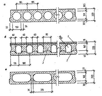
Prefabricated reinforced concrete floor elements are made in the form of hollow-core decking, resting on walls or in the form of panels resting on girders. The actual length of the flooring is 3 cm less than the nominal size, and the panels are 1 cm less. The actual width of the floorings and panels is 1 cm less than the nominal one. This circumstance must be taken into account when marking the axes for the load-bearing walls of the house. Large panels differ from decking mainly in their dimensions (Figure). They are made in factories, giving the surfaces of the ceilings a texture ready for painting. For low-rise buildings, ribbed panels and floorings of 1.2 x 6 m are often used for interfloor floors (Figure).
Grade 300 concrete is used for heavy load floorings, and 200 grade concrete for normal ones. For panels, only grade 200 concrete is used. welded mesh from hot-rolled steel of a periodic profile. In the manufacture of panels, in most cases, they use pre-stress fittings.
The decks and floor panels are marked with an alphabetic and a numeric part. The first letter "H" or "P" corresponds to the name of the product (deck or panel), the second letter "" D indicates that the deck or panel is designed for heavy load. The first two digits indicate the nominal length of the deck or panel, the second two digits their nominal width.
The loads on the floors of residential buildings are made up of the calculated temporary (mass of furniture, equipment; people in the room, etc.) and the calculated constant loads. In this case, special attention should be paid to the loads from the installed plumbing equipment (boilers, baths, etc.), the load for which is considered separately. The calculated constant load is understood as the own weight of structures and it depends on the type of floor, insulation, etc. For attic floors, the calculated live load is usually taken to be 1050 N / m 2, and for basement and interfloor floors - 2100 N / m 2. Panels as right-
the forks are laid on the load-bearing wall, and the length of the surface on which they rest should be at least 10-15 cm. If the panel thickness is more than 10 cm, the length of the supporting surface should not be less than the thickness of the slab. The panels are installed on the bed from the solution on which the brickwork... Aligns decks and panels horizontally and on the bottom surface that serves as the ceiling
For the convenience of fastening, the prefabricated panels are equipped with special loops for slinging. Mounting hinges are made of round reinforcing steel and are embedded in the slabs during their manufacture. When installing reinforced concrete floorings, make sure that their reinforcement is in the place where the flooring experiences tensile stress, i.e. in floor panels - at the bottom, in consoles - at the top.
The advantage of hollow core panels and decking lies in the increased heat and sound insulation characteristics. Less concrete is required for their manufacture, which significantly reduces the weight and, consequently, the load on the load-bearing walls. The advantage of prefabricated floors is that they can be loaded immediately after installation. In addition, precast concrete floors are robust and durable (over 80 years).
The disadvantages of reinforced concrete floors include increased sound permeability. Another significant disadvantage of prefabricated reinforced concrete floors is the fact that their installation is practically impossible without lifting equipment.
Overlapping on reinforced concrete T-section beams is arranged with filling the interbeam space with lightweight concrete or hollow slabs (Figure). The seams between the beams and slabs are filled with cement mortar and rubbed over. Attic and basement floors must be insulated, interfloor soundproofed. To do this, use expanded clay or sand bedding, layered coatings with elastic gaskets. In this case, it is desirable that heat and sound insulation is not carried out due to an increase in the weight of building structures.
Monolithic floors are made according to the installed formwork. Transferring loads from the floor to the load-bearing walls, monolithic ceilings serve as an additional rigid frame of the building. Their device requires a certain professional skill and should be carried out according to the project under the guidance of a specialist - builder. On-site production of slabs has its advantages. This does not require special transport and lifting equipment. Small-scale mechanization is sufficient for lifting and moving concrete. The basis monolithic floors the Monier slab is laid, in which the reinforcement is placed in places of tension, that is, in the lower part of the slab. This is because steel has 15 times the tensile strength of concrete. Reinforcement cage the slabs must be located at a distance of at least 3-5 cm from the walls of the formwork so that concrete can fill it
|
|
 Drawing. Overlappings on reinforced concrete beams (dimensions in mm): A- with interbeam filling in the form of lightweight concrete slabs: B- with filling of interbeam voids with hollow lightweight concrete blocks; 1 - reinforced concrete beams: 2 - lightweight concrete slabs: 3 - hollow blocks: 4 - cement mortar; 5 - backfilling with slag (sand): 6 - soundproofing pad: 7 - logs; в - gasket (hardboard); 9 - roofing paper; 10 - slag concrete; 11 - fell from linoleum on mastic: 12 - plank floor
space. The length of the span overlapped monolithic slabs, should not exceed 3 m. For pipelines of plumbing communications, special metal or vinyl sleeves with an inner diameter larger than the pipeline being laid are installed in the ceiling. The gap between the sleeve and the pipeline is minted with tarred tow.
The disadvantages of monolithic floors include the need to install wooden formwork almost over the entire area of the house, however, this does not mean that the formwork must be exposed all at once. Overlapping can be performed in separate spans, transferring the formwork as the concrete sets.
The bearing capacity of monolithic floors is provided by reinforcement, the diameter of which must be at least 8-12 mm. In this case, intermediate joints of the rods along the entire length of the overlap are undesirable. The minimum layer of concrete on the outside of the slab must be at least 2 cm. The span must be concreted in one working cycle.
Interfloor structures.
Interfloor overlap is one of the most difficult and critical parts of a building, requiring 20-25% of the total labor costs for construction. The cost of overlapping with floors reaches 25-30% of the cost of general construction works. Therefore, the choice of a rational design of the interfloor overlap largely determines the technical and economic qualities of a large-panel building.
The intermediate floor is a complex enclosing structure consisting of floor elements, a sound-insulating layer and a load-bearing part with a ceiling surface prepared for painting. Each of these parts of the overlap has its own
certain requirements.
Rice. 2.7. Types of load-bearing floor panels:
a) flat solid; b) flat with round voids; c) ribbed; d) often ribbed; e) tent type.

 Rice. 2.8. Large-panel floor plans (by sound insulation properties).
a) acoustically homogeneous overlap; b, c, d) acoustically inhomogeneous floors of a separate type; b) overlap with split floor; c) with a separate self-supporting and suspended ceiling; d) a slab with a split ceiling and floor covering to improve impact sound insulation.
1. Carrier Zh.B. panel; 2. floor covering, including layers of elastic-soft material; 3. element of a split floor; 4. strip soundproofing pads; 5. solid soundproofing layer; 6. split ceiling element; 7. soundproof suspension (mountings); 8. air gap.

Rice. 2.9. Large-panel slabs of a separate type with a lightweight concrete floor panel: a) with a flat bearing panel; b) with a ribbed panel; c) with a tent-type panel; 1-carrier panel; 2-piece concrete floor panel; 3-soundproof filling; 4-elastic soundproofing pad; 5-linoleum mastic.

a) platform joint; b) platform-toothed joint; c) contact joint with support of floor panels on outboard cantilever wall panels; d) contact-nail joint. Examples of wall fixation: e) platform joint; f) contact joint: 1-wall panel; 2-panel overlap; 3-solution; 4-mounting hinges; 5-welded joints; 6-slots in the floor panel; 7-bolt connections of tie pads; 8-anchor nut; 9-f.b. retainer for inner panels; 10-pin lock with adjustable nut; 11-cement plasticized paste; 12-steel washer with plastic spacer; 13-grooves in the floor panels for the passage of the retainer; 14-slot in the wall panel; 15-protrusion (spike) of the wall panel.
The floors must be durable, have the required hardness, impact strength, impermeability, moisture, meet the requirements of heat assimilation and have a good decorative appearance.
The purpose of the soundproofing layer is to provide the required sound insulation from impact noise and improve sound insulation from airborne noise; it must have the necessary bearing capacity and deformability, be biostable and not change its properties over time under the action of a load,
Strength and rigidity are the main requirements for the load-bearing part of the floor. The ceiling must have increased crack resistance and reduced deformability; in some cases, it must have sound absorption capacity and high decorative effect.
The main types of load-bearing floor panels are flat, ribbed and hipped-roof panels with ribs along the contour (see Fig. 2.7), which you reviewed in the last semester.
Flat panels (Fig. 2.7.a, b) are made solid and hollow. The lightening of the panels with voids gives savings in the consumption of steel and concrete, but causes a significant increase in their construction height and worsens the sound insulation qualities. As a consequence, it is advisable to give preference to solid panels,
Solid panels for a room are made of heavy concrete M 150-200 with spans of 2.6-3.2 m and have a thickness of 120-140 mm and 160 mm. Panels can also be made from expanded clay concrete, slag concrete and other lightweight concrete of grades not lower than 100. The simplicity of the shape of solid panels greatly facilitates their manufacture, and the low height makes it possible to increase the height of the room. The smooth surfaces of the panels are ideal for floors and ceilings.
With a wide pitch of supporting structures (6m -_6.4m), the use of solid floor panels is impractical, since their thickness increases accordingly, and they turn out to be very heavy. In these cases, hollow-core prestressed floor panels with a thickness of 220 mm are used. The width of these panels is taken from 0.8 to 2 m with a graduation of 200 or 300 mm in order to be able to obtain the required set of panels at any distance between staircases or any width of the building, corresponding to the modular system.
Ribbed panels (see Fig. 2.7. C, d) are made of heavy concrete and may have a rare and frequent arrangement of intermediate ribs. When constructing ceilings, they are laid with the ribs up. A floor slab is laid on them on sound-proof gaskets.
The hipped-roof panel (Fig. 2.7, d.) Is a flat reinforced concrete panel. a slab with a thickness of 50-60 mm, bordered along the contour by ribs with a height of about 200 mm. The production of hipped roof panels is relatively difficult from a technological point of view. These panels have a small structural thickness, allow to increase the height of the room, while the cost of such ceilings is lower in comparison with ceilings made of hollow-core decking, a significant disadvantage of hipped-roof panels is the presence of ribs along the contour, which creates a rigid planning scheme of the building, requiring the placement of partitions directly under the ribs.
Large-panel floors are classified:
a) by constructive type(as soundproofing fences);
b) according to the settlement scheme;
c) by weight of the mounting element.
By constructive type (as sound-insulating barriers), the floors are divided (Fig. 2.8):
a) to acoustically homogeneous (see Fig. 2.8, a);
b) to acoustically inhomogeneous - separate type (see Fig. 2.8.b-d.)
An acoustically homogeneous floor consists of a load-bearing panel, the lower surface of which is the ceiling, and a floor covering that includes a layer of elastic material, such as linoleum, which improves the sound insulation of the floor against impact noise (see Figure 2.8, a).
The slab of a separate type consists of a load-bearing panel, a floor or a ceiling of a separate structure and a sound-insulating layer, which is an air space either free or completely or partially filled with an elastic-soft sound-insulating material.
Split-type slabs are divided into two groups:
a) with a split floor (see Fig. 2.8.b);
b) with a separate self-supporting or suspended ceiling (see Fig. 2.8, c, d).
An overlap with a split ceiling can be supported by a load-bearing part through sound-insulating gaskets or have a floor covering that includes an elastic-soft layer that improves insulation against impact sound (see Figure 2.8, d).
Figure 2.9 shows split slabs with gypsum concrete floor panels laid on load-bearing reinforced concrete panels of various designs.
A structure of this type is also a separate panel floor made of two often ribbed reinforced concrete. plates (Figure 2.9.1.). The floor slab rests freely on the extreme edges of the lower slab through elastic gaskets, which are made of asbestos cement, soft fiber board, fiberglass boards and other materials. This overlap is distinguished by a high degree of factory readiness, ease of installation and satisfactory soundproofing qualities, but it requires a large consumption of metal (8.7 kg / m2) and concrete.
In the second solution to a separate floor structure, reinforced concrete is used as a load-bearing structure. floor panel Acoustic fiberboard ceiling, on which the interlayer of mineral wool or any other soundproof materials, suspended from the floor panel or rests on the wall panels independently, forming a continuous air gap within the ceiling structure (Fig. 2.9.1, b).
This construction is distinguished by its relatively low weight (200-220 kg / sq.m) and has good sound insulation qualities.
According to the design scheme, panel floors are classified:
a) on floors with free-lying panels;
b) on ceilings with panels clamped on supports:
c) on continuous floors with panels, the joints of which perceive the support moments.
The weight of the ceiling mounting element (taking into account the weight of the rigging devices) is determined by the lifting capacity of the erection crane.
The most common types of floor structures for large-panel houses with transverse load-bearing walls are:
In the form of a flat reinforced concrete slab with a thickness of 14-16 cm (series 1605, 1-464, etc.).
For large-panel houses with load-bearing longitudinal walls, hollow-core decking 22 cm thick and 0.8 wide is used; 1.2; 1.6 and 2.0 m.V recent times there is a tendency towards the use of solid flat prestressed rail. b. panels with a thickness of 16 cm.
Lecture. Slabs and floors for multi-storey panel residential buildings
In large-panel residential buildings, prefabricated reinforced concrete floors of the following types are used:
- from solid reinforced concrete slabs;
- from solid slabs with edges along the contour (Fig.);
- two-layer ribbed slabs (slabs with a false ceiling);
- from hollow-core decking (fig.)
Hollow-core floor panels:
a - with round voids; b - manufactured on installations with concreting combines (1 - top layer; 2 - bottom layer; 3 - middle layer); c - with oval voids
In industrial housing construction, solid-section floor panels with a thickness of 140, 160 mm and hollow-core panels with a thickness of 220 mm are used.
Reinforced concrete solid floor slabs for large-panel buildings.
The panels are used in the cross-wall structural system of buildings at a step cross walls(multiples of 300 mm) 2.4 - 4.2 m, the length of the slabs reaches 7.2 m (multiple of 600 mm), the thickness is taken from 100 to 200 mm.
Reinforced concrete solid floor slabs for large-panel buildings are divided into types according to their thickness and the pattern of support on wall panels:
- 100 mm thick, supported on 4 sides;
- 120 mm thick, supported on 2 and 4 sides;
- thickness 140, 160, 180, 200 mm, support on 2, 3 and 4 sides.
V modern construction the most widespread are slabs made of heavy concrete with a thickness 160 mm.
The slabs are supported on the walls along the contour (4 sides) with a small step of the transverse walls, on three sides - with a small step of the transverse walls or on two opposite sides with a large step of the transverse walls. Thus, the working reinforcement of the slabs is placed in two or three directions.
Slabs L≥4.8 m long are designed to be supported on 2 sides and have prestressed reinforcement.
Coordination dimensions of the slabs:
- length - 3.0 - 7.2 m (after 0.3);
- width - 1.2 - 6.6 m (through 0.3).
The length of the slab is taken as:
- the smallest of the dimensions of the slab in plan when supported on 4 sides,
- the dimension of the side of the slab that does not rest on bearing structures when leaning on 2 or 3 sides.
According to the operating conditions, one of the dimensions should not exceed 3.6 m.
Plates have:
- steel embedded parts, reinforcement outlets and others structural elements for connection with other building structures;
- channels of hidden electrical wiring, a socket for boxes and sockets, plastic boxes with anchors for fixing lamps;
- openings and openings for the passage of utilities.
The lateral edges on the sides of the slabs, intended for connection in the span (without leaning on the walls), are performed with closed or open recesses, the shape of which ensures the joint work of the connected slabs for shear in the horizontal and vertical directions after the grouting of the joints between the slabs. The slabs can be recessed to form dowels on the sides, which are supported by the wall panels.
The depth of the platform for supporting the slabs on the outer walls - 90 mm. The nominal size of the depth of the platform bearing on interior walls is half the thickness of the wall panel minus 10 mm. Supporting the slabs on the walls of the staircase - for the entire thickness of the wall. The floor slabs are supported on a cement-sand mortar. All steel connections between floor slabs and external wall panels are welded. At least two ties are provided on each side of the floor slab.
Panels are made of heavy concrete of class B15 or more, or lightweight concrete on porous aggregates of class B12.5. The protective layer is not less than 15 mm.
Floor panel 120 mm thick has two lifting loops on one side length, on the other - embedded parts for welding with lifting loops of the panel, which is laid side by side in the ceiling. At each beveled corner of the panel, reinforcement outlets are provided, which are welded to the outlets of adjacent floor panels. The lifting eye, parallel to the panel surface, protrudes 70 mm beyond the panel edge. Accordingly, the embedded part of the steel corner is recessed by 80 mm. The reinforcement outlet at the corner of the panel is bent at an angle of 90 ˚.
Solid panels are cut or recessed to form dowels. In solid panels, channels with a diameter of 25 mm are arranged for hidden replaceable wiring.
Solid floor panels 160 mm thick used for residential buildings with small and large cross-wall pitch. The panels are used in conjunction with heat-insulating floors. These panels in Kiev have 6 lifting loops and 2 embedded parts on each side.
GOST 12767-94
INTERSTATE STANDARD
FLOOR PLATES
REINFORCED CONCRETE CONTINUOUS
FOR LARGE PANEL BUILDINGS
GENERAL TECHNICAL CONDITIONS
INTERSTATE SCIENTIFIC AND TECHNICAL COMMISSION
FOR STANDARDIZATION AND TECHNICAL REGULATION
IN CONSTRUCTION (MNTKS)
Moscow
Foreword
1 ... DEVELOPED by the Central Research and Design Institute for Typical and Experimental Design of Dwellings (TsNIIEP of Dwellings) and the Research, Design and Engineering and Technological Institute of Concrete and Reinforced Concrete (NIIZHB) Russian Federation.
INTRODUCED by the Ministry of Construction of Russia
2 ... ACCEPTED by the Interstate Scientific and Technical Commission for Standardization and Technical Regulation in Construction (ISTC) on November 17, 1994.
|
State name |
The name of the government building authority |
|
Republic of Armenia |
State Supraarchitecture of the Republic of Armenia |
|
The Republic of Kazakhstan |
Ministry of Construction of the Republic of Kazakhstan |
|
Republic of Kyrgyzstan |
Gosstroy of the Kyrgyz Republic |
|
Russian Federation |
Ministry of Construction of Russia |
|
The Republic of Tajikistan |
Gosstroy of the Republic of Tajikistan |
|
The Republic of Uzbekistan |
Goskomarkhitektstroy of the Republic of Uzbekistan |
3 ... PUT INTO EFFECT from January 1, 1996 as a state standard of the Russian Federation by the Decree of the Ministry of Construction of Russia dated 05/18/95 No. 18-45
4 ... REPLACEGOST 12767-80
GOST 12767-94
INTERSTATE STANDARD
REINFORCED CONCRETE FLOOR PLATES, CONTINUOUS FOR LARGE-PANEL BUILDINGS
Generaltechnicalconditions
Reinforced concrete solid slabs for floors in large-panel buildings. General specifications
dateintroduction 1996-01-01
1 area of use
This standard applies to solid reinforced concrete slabs (hereinafter referred to as slabs) made of heavy concrete, structural lightweight concrete of a dense structure and dense silicate concrete and intended for use as a bearing part of the floors of large-panel buildings for various purposes with an estimated floor load (excluding their own slab weight) up to 6.0 kPa incl.
The standard establishes the mandatory requirements set out in clauses - and sections -.
The standard does not apply to reinforced concrete slabs with protruding parts to form balconies.
2. Normative references
Throughout this standard, references are made to the following standards:
The type of slabs when they are supported on supporting structures
on four sides
on three sides
on both sides
3.3 ... The shape and dimensions of the slabs must correspond to the established working drawings for these slabs.
3.4 ... The structural length and width of the slab are taken according to GOST 28984 equal to the corresponding coordination dimension of the slab, reduced by the gap between adjacent slabs.
When developing working drawings for slabs of mass use, the gap between adjacent slabs should be taken equal to 20 mm (Figure a).
If it is necessary to overlap with a slab a space that exceeds the distance between adjacent coordination axes of a building, the structural length of the slabs (for example, slabs resting on the walls of the staircase of large-panel buildings with transverse load-bearing walls) is taken equal to the distance between the axes, increased by the required value a, determined in accordance with with the adopted constructive decision (Figure b, c).
3.5 ... It is recommended to take the coordination length and width of the slabs in the development of new projects of residential large-panel buildings in accordance with the table taking into account the maximum lifting capacity of the assembly cranes.
Coordination dimensions of the slab, mm
4800; 5400; 6000
2400; 3000; 3600
1200; 2400; 3000; 3600
Note - The length of the slab is taken as follows:
When it is supported on four sides - the smallest of the dimensions of the slab in the plan;
When it is supported on three or two sides - the size of the side of the slab that is not supported by the supporting structure.
The lateral edges on the sides of the plates of the PD and PT types, intended for joining in the span (without leaning on the supporting structures of the building), should be performed with closed or open recesses, the shape of which should ensure the joint operation of the mating plates for shear in the vertical and horizontal directions after grouting the seams between the plates.
On the underside of these edges of the slabs, there should be 10 mm chamfers at an angle of 45° .
The slabs can have recesses for the formation of dowels also on the sides, supported by the supporting structures of the buildings.
Slabs intended for use in areas with a design seismicity of 7 - 9 points can be made with indentations for embedding metal ties and the formation of dowels.
3.10 ... Plates must have:
Steel embedded parts, reinforcement outlets and other structural elements intended for connection with adjacent building structures;
Channels for hidden electrical wiring, sockets for junction boxes and sockets, plastic boxes with anchors for fixing luminaires;
Openings and openings for the passage of utilities.
3.11 ... For lifting and installation of slabs, mounting loops or special gripping devices are used, the design of which is set by the manufacturer in agreement with the consumer and the design organization - the author of the building (structure) project. The location and dimensions of the holes in the plates provided for loopless mounting are taken according to the drawings that are part of the design documentation for the gripper for these plates.
Plates made in vertical molds (cassettes) must have hinges designed to remove the plates from the mold.
3.12 ... Plates are used taking into account their fire resistance limit specified in the working drawings of the plates, based on tests in accordance with GOST 30247.0 and GOST 30247.1.
3.13 ... Plates are designated by marks consisting of alphanumeric groups separated by hyphens.
) and overall dimensions (length, width) of the slabs in decimeters, the values of which are rounded to the nearest whole number.In the second group, they give:
The design load on the slab (without taking into account the load from its own weight) in kilopascals or the serial number of the slab established by the design documentation according to its bearing capacity;
Class of prestressed reinforcement (for prestressed slabs);
For slabs made of lightweight and dense silicate concrete, its additional type (l - lightweight concrete, c - dense silicate concrete).
In the third group, if necessary, indicate additional characteristics of the plates, reflecting the special conditions of their use (for example, resistance to seismic effects is indicated by the letter "C" and a number corresponding to the calculated seismicity in points), as well as designations design features slabs (the presence of openings, bevels).
Example of a symbolslabs of type 2P, 3580 mm long, 5980 mm wide for a design load of 3.0 kPa, with prestressing reinforcement, made of lightweight concrete:
2 P 36.60-3L
The same, 4PD slabs 5980 mm long, 2380 mm wide for a design load of 6.0 kPa, with prestressing reinforcement of class At-V, made of heavy concrete:
4 PD 60.24-6AmV
Note - It is allowed to accept the designations of the brands of plates in accordance with the working drawings of the plates.
4. General technical requirements
4.1 ... Plates are manufactured in accordance with the requirements of this standard and the technological documentation approved by the manufacturer, containing requirements for the manufacture of plates at all stages of the production process, according to project documentation, approved in accordance with the established procedure.
Slabs intended for use as slabs of loggias of buildings must satisfyadditional requirements GOST 25697.
4.2 ... Plates are subject to manufacture in molds that ensure compliance with the quality and accuracy requirements for the manufacture of plates established by this standard.
4.3 ... Plates must meet the design requirements for strength, stiffness and crack resistance.
4.3.1 ... The strength, stiffness and crack resistance of slabs is assessed by loading tests before the start of their mass production, when constructive changes or changes in their manufacturing technology are introduced into them, as well as in the process of serial production of slabs in cases where this is provided for by the working drawings of specific slabs - periodically in time installed by these drawings.
4.3.2 ... The strength, stiffness and crack resistance of the slabs are ensured by observing a set of standardized and design indicators characterizing the geometric dimensions of the slabs, the strength of concrete, the type and physical and mechanical properties of reinforcing steel, the size of reinforcing products and the strength of their welded joints, the location of reinforcement and reinforcing products, the thickness of the concrete cover , which are checked in accordance with the requirements of this standard in the process of incoming, operational and acceptance control.
4.4 ... Slabs should be made of heavy concrete with an average density of more than 2200 to 2500 kg / m 3 inclusive, structural lightweight concrete of a dense structure with an average density of at least 1500 kg / m 3 or dense silicate concrete of an average density of at least 1800 kg / m 3 classes (grades) by the compressive strength established by the design documentation.
4.5 ... The actual strength of concrete must correspond to the required strength assigned by GOST 18105 depending on the rated strength (class or grade for compressive strength, transfer and tempering) and on the characteristics of the actual homogeneity of concrete strength.
4.6 ... The normalized transfer strength of concrete of prestressed slabs, depending on the class (grade) of concrete in terms of compressive strength, type and class of prestressed reinforcement, must correspond to that specified in the design documentation.
4.7 . Requirements for the tempering strength of concrete
4.7.1 ... The value of the normalized tempering strength of concrete for compression of prestressed slabs made of heavy or light concrete is taken to be equal to the value of the normalized transfer strength, and of slabs with non-stressed reinforcement - 70% of the strength of concrete corresponding to its class (brand).
4.7.2 ... When slabs are delivered in the cold season, as well as to ensure their safety during transportation by rail (as agreed with the slab consumer), the normalized tempering strength of slab concrete can be increased to 85% of the strength of concrete corresponding to its class (brand).
4.7.3 ... The normalized tempering strength of concrete slabs made of dense silicate concrete should be equal to 100% of the compressive strength of concrete corresponding to its class (brand).
4.7.4 ... Delivery of slabs with a concrete tempering strength lower than the strength corresponding to its class (grade) in terms of compressive strength is carried out on condition that the manufacturer guarantees that the concrete slabs of the required design strength, determined by the results of testing control samples made from a concrete mixture of a working composition, stored in conditions according GOST 18105 and tested at the age of 28 days.
4.8 ... Frost resistance and water resistance of concrete slabs must correspond to its brands in terms of frost resistance and water tightness, established by the design documentation of a particular building and specified when ordering the slabs.
4.9 ... The quality of the materials used for the preparation of concrete must ensure that the technical requirements established by this standard for concrete slabs are met.
4.10 ... Concrete, as well as the materials used for its preparation, must meet the requirements:
Heavy concrete - GOST 26633;
Lightweight concrete - GOST 25820;
Dense silicate concrete - GOST 25214.
4.11 . Requirements for reinforcement, reinforcement and embedded products
4.11.1 ... The type and class of reinforcing steel used for reinforcing slabs must correspond to the established working drawings of specific slabs.
4.11.2 ... The shape and dimensions of reinforcement and embedded products and their position in the slabs must correspond to those indicated in the working drawings of the slabs.
Welded reinforcement and embedded products must meet the requirements of GOST 10922.
4.11.3 ... Reinforcing steel used for reinforcing slabs in accordance with the working drawings must meet the requirements:
prestressing reinforcement:
Rod thermomechanically hardened of classes At-IV, At-V and At-VI (regardless of its weldability or resistance to corrosion cracking) - GOST 10884;
Hot-rolled rods of classes A-V, A-VI - GOST 5781;
stress-free fittings (including distribution):
Rod thermomechanically hardened classes At-IIIС and At-IVС - GOST 10884;
Rod hot-rolled smooth and periodic profile grades A-I, A-II and A-III - GOST 5781;
Reinforcing wire of periodic profile of class Вр-1 GOST 6727, classes Вр500 and Вр600 - current regulatory documents.
Used as prestressing reinforcement of slabs manufactured by continuous formless molding on long benches or by continuous reinforcement with reinforcement tension on stops, reinforcing ropes of class K-7 must meet the requirements of GOST 13840.
The tensioned reinforcement of plates made of strengthened hood with control of elongation and stress or only elongation of reinforcing steel of classes A-III in accordance with GOST 5781 and At-IIIC in accordance with GOST 10884 must meet the requirements of technological documentation.
4.11.4 ... Grades of reinforcing steel, as well as grades of rolled products made of ordinary quality carbon steel or low-alloy steel used for the manufacture of embedded products, must correspond to those established by the design documentation of a particular building or specified when ordering slabs.
4.11.5 ... Mounting loops should be made of smooth reinforcing steel of the class A-I stamps St3ps and St3sp by GOST 5781.
Reinforcing steel grade St3ps is not allowed to be used for mounting hinges of plates, the lifting and installation of which is possible at an air temperature below minus 40° WITH.
For mounting hinges of plates, it is allowed to use instead of reinforcing steel class A-I grades St3ps and St3sp in accordance with GOST 5781 hot-rolled round steel, respectively, grades St3ps2-1 and St3sp2-1 in accordance with GOST 535.
4.11.6 ... In the cases stipulated by the design documentation, reinforcement and embedded products, reinforcement outlets and connecting elements must have an anti-corrosion coating, type and specifications which must comply with the established design documentation.
4.12 ... The values of stresses in prestressing reinforcement and their actual deviations, controlled after the end of tension on the stops, must correspond to those indicated in the working drawings of the plates.
4.13 ... The heating temperature of prestressed bar reinforcement with the electrothermal method of its tension should not exceed 450° WITH.
4.14 ... The transfer of compression forces to concrete (release of tension of prestressing reinforcement) should be carried out after the concrete slabs reach the required transfer strength, which is assigned depending on the rated transfer strength (4.6).
4.15 ... Actual deviations geometric parameters plates should not exceed the limit indicated in the table .
Table 3
in millimeters
|
Geometric parameter name |
Prev off |
|
|
Deviations from linear dimensions |
Slab length and width: |
|
|
Up to 4000 incl. |
± 8 |
|
|
± 10 |
||
|
Slab thickness |
± 6 |
|
|
The size of the cutouts, protrusions |
± 6 |
|
|
Size defining position: |
||
|
Holes, cutouts, plastic boxes with anchors and junction boxes |
||
|
Embedded products: |
||
|
in the plane of the slab |
||
|
from the plane of the slab |
||
|
Deviation from the straightness of the profile of the upper surface of the slab intended for direct gluing of linoleum, as well as the profile of the lateral edges of the slab: |
||
|
Length 2000 |
||
|
Full length |
||
|
The deviation from flatness of the front lower (ceiling) surface of the slab when measured from the conditional plane passing through three corner points of the slab with the length: |
||
|
The difference in the diagonals of the slab length: |
||
|
Note - By agreement with the design organization - the author of the project of a specific building (structure), it is allowed to take values marginal deviations geometric parameters different from the above, based on the calculation of accuracy in accordance with GOST 21780, taking into account constructive solution buildings (structures) and the conditions of its construction. |
||
4.16 ... Actual deviations of the thickness of the concrete cover to the reinforcement from its nominal value specified in the working drawings of the slabs should not exceed the limit specified in GOST 13015.0.
4.17 ... To accommodate hidden replaceable electrical wiring, plastic tubes should be used. The actual diameter of the channels of the electrical wiring being replaced should not be less than 0.9 of their nominal diameter.
4.18 ... Requirements for the quality of concrete surfaces and outward appearance slabs - by GOST 13015.0.
4.19 ... Cracks are not allowed in the concrete of the slabs supplied to the consumer, with the exception of shrinkage and other surface technological cracks on the lower (ceiling) surface of the slabs no more than 0.2 mm wide.
4.20 ... Reinforcement exposure is not allowed, except for outlets or ends of prestressing reinforcement, which should not protrude beyond the end surfaces of the slabs by more than 10 mm and should be protected with a layer of cement-sand mortar or bitumen varnish.
4.21 ... Open surfaces of steel embedded products, reinforcement outlets, slinging holes and mounting (lifting) loops must be cleaned of concrete influx.
4.22 . Marking
4.22.1 ... Plate marking - by GOST 13015.2.
Markings and signs should be applied to the side edge or top surface of the slab.
4.22.2 ... On the upper surface of the slab, supported on three sides, signs "Place of support" should be applied along GOST 13015.2 , located in the middle at each side of the support of the slab.
4.22.3 ... The slabs shall bear the designation of the upper surface of the slab and the direction of the working span for slabs supported on two or three sides.
5. Acceptance rules
5.1 ... Acceptance of plates is carried out in batches in accordance with GOST 13015.1 and this standard.
5.2 ... Input control according to the documents certifying the quality of the materials used for the preparation of concrete (binders, aggregates, water, additives) and the quality of reinforcing steel and rolled metal, establish their compliance with the requirements of section , and also carry out a direct check of their quality and the necessary tests in accordance with the technological documentation.
5.3 ... Acceptance of plates is carried out according to the results:
Acceptance tests of each batch of slabs - in terms of concrete strength (class or brand in terms of compressive strength, transfer and tempering), compliance of reinforcement, reinforcement and embedded products, strength of their welded joints, tension of prestressing reinforcement, accuracy of geometric parameters, concrete cover thickness up to reinforcement, the presence and location of embedded products and outlets of reinforcement, mounting loops or slinging holes, the type and technical characteristics of the anti-corrosion coating of reinforcement and embedded products, outlets of reinforcement and connecting elements (in cases stipulated by the design documentation), the quality of the concrete surface of the slabs and their appearance , the correctness of the application of markings and signs;
Periodic tests - in terms of frost resistance and water resistance of concrete.
5.4 ... Periodic tests for strength, stiffness and crack resistance of slabs by loading, if provided for by the working drawings of specific slabs, are carried out in accordance with GOST 8829 within the time frame established by these drawings.
The strength, stiffness and crack resistance of plates, the loading tests of which are not provided for by the working drawings, is ensured by the observance of a set of standardized and design indicators specified in, which are checked in accordance with the requirements of this standard.
5.5 ... In cases where it is established during the control that the tempering strength of concrete slabs does not meet the requirements specified in , the delivery of such slabs to the consumer should be made only after the concrete reaches the strength corresponding to the class (brand) in terms of compressive strength.
5.6 ... Acceptance of slabs in terms of accuracy of geometric parameters, thickness of concrete cover to reinforcement, location of embedded products and reinforcement outlets, quality of concrete surface, controlled by measurement, is carried out according to the results of selective one-stage control.
5.7 ... Based on the results of acceptance, a document is drawn up on the quality of the supplied boards in accordance with GOST 13015.3.
Additionally, the quality document should contain:
Concrete grades of slabs for frost resistance and water resistance;
The class of reinforcing steel used as prestressing reinforcement of plates (At-VI, A-VI, At-V, A-V, At-IV);
Grades of reinforcing steel of classes A-I and A-III, as well as grades of rolled products from carbon steel of ordinary quality or low-alloy steel, from which embedded products and mounting loops are made.
6. Methods of control
6.1 ... Loading tests of slabs to control their strength, stiffness and crack resistance (if provided by the working drawings of the slabs) are carried out in accordance with GOST 10922.
6.4 ... Measurement of stresses in prestressing reinforcement, controlled at the end of its tension on the stops, - according to GOST 22362.
6.5 ... The dimensions of the slabs, deviations from the straightness of the profile of their upper surface and the profile of the side faces, deviations from the flatness of the front lower (ceiling) surface, the difference in the diagonals of the slab, the size and position of reinforcement and embedded products, outlets of reinforcement and mounting loops or slinging devices, as well as the quality of concrete the surfaces of the slabs are checked by the methods established GOST 26433.0 and GOST 26433.1.
6.6 ... The position of the reinforcement in the slab, as well as the thickness of the concrete cover to the reinforcement, is determined by GOST 17625 and GOST 22904.
In the absence of the necessary instruments, cutting of grooves and exposure of slab reinforcement with subsequent sealing of grooves is allowed. Furrows may be cut at a distance from the ends of the slabs not exceeding 0.25 of the slab length.
6.7 ... The diameter of the channels and tubes for the removable wiring is checked by pulling through them along the entire length of a steel ball-shaped gauge with a diameter equal to 0.9 of the nominal diameter of the channel (tube) specified in the working drawings of the plates.
The gauge must be attached to a flexible cable. Deviation of the actual diameter of the gauge from the nominal should not exceed 0; -0.2 mm.
6.8 ... Control of the presence of embedded products, outlets of reinforcement, mounting loops or slinging devices, cleaning from concrete flows, the presence of an anti-corrosion coating, the presence of grease and rust stains on the front surfaces of the slabs, the correctness of the application of markings and signs - by external inspection.
7. Transportation and storage
7.1 ... Transportation and storage should be carried out in accordance with the requirements GOST 13015.4 and this standard.
7.2 ... Plates should be stored in a vertical position - in cassettes, in an inclined position - according to the diagrams given in the design documentation, or horizontally - in stacks, the height of which should not exceed 2.5 m.
7.3 ... When storing horizontally and in an inclined position, spacers must be placed between the plates, ensuring a minimum allowable gap between the plates of at least 10 mm.
When using inelastic spacers for stacking, they should be placed one above the other vertically along the line of lifting devices (hinges, holes) or in the immediate vicinity of them:
For prestressed slabs, parallel to the short side;
For slabs reinforced with non-tensioning reinforcement, parallel to the long side.
7.4 ... In the vertical or inclined position, the slabs are transported on special panel trucks equipped with gaskets and clamps with elastic gaskets, ensuring the immobility of the slabs and the safety of the front surfaces and parts protruding from the plane of the slabs. insulation of airborne noise with a slab without a floor
reduced impact noise level under a slab without a floor
Maximum pitch of transverse load-bearing walls, m
Floor structures that can be used in residential buildings slabs of the specified type
Wooden floor on logs; covering from fibreboard, baseless linoleum, block parquet on the screed and soundproofing layer; linoleum coating on a heat and sound insulating base on a screed
3P, 3PT, 3PD
4P, 4PT, 4PD
6.6 (for mixed
The same, as well as a linoleum coating on a heat-insulating base without a screed
5P, 5PT, 5PD
6P, 6PT, 6PD
Note - The parameters of the floor (floor mass, material of the sound-insulating layer, etc.) should be taken by calculation (in accordance with the current regulatory documents) from the condition of ensuring the standard values of the airborne sound insulation indices and the reduced level of impact noise.
Key words: floor slab, reinforced concrete, bearing part of floors, large-panel buildings, floor
