How does the electric current flow. What is Electric Current? Conditions for the existence of an electric current: characteristics and actions. Danger of electric current and other dangerous properties of electricity and safety precautions
Free electrons .. Electric current .. Measuring current .. Ammeter .. The unit of current is Ampere .. Direction of electric current .. Direction of movement of electrons ..
When an electric field is applied to a conductor, free electrons (carriers of a negative charge) begin to drift in accordance with the direction of the electric field - a electricity.
The movement of electrons means the movement of negative charges, therefore, - electric current is a measure of the amount of electrical charge carried across the cross-section of a conductor per unit of time.
In the international SI system, the unit of measure for charge is Coulomb, and the unit of time is the second. Therefore, the unit of current strength is Coulomb per second (C / sec).
Current measurement
Current unit The pendant per second in the SI system has a specific name Ampere (A)- in honor of the famous French scientist André-Marie Ampere(pictured in the title of the article).
As we know, the magnitude of the negative electric charge of an electron is 1.602 10 -19
Pendant. Therefore, one Coulomb of electric charge consists of 1 / 1.602 10 -19
= 6,24 10 18
electrons.
Therefore, if 6.24 10 18
electrons cross the cross section of the conductor in one second, then the magnitude of this current is equal to one ampere.
To measure the amperage there is a measuring device - an ammeter.
Rice. 1
Ammeter is included in the electrical circuit ( rice. 1) in series with that element of the circuit, the current strength in which it is necessary to measure. When connecting the ammeter, the polarity must be observed: the "plus" of the ammeter is connected to the "plus" of the current source, and the "minus" of the ammeter - to the "minus" of the current source.
Direction of electric current
If in the electrical circuit shown in rice. 1 close the contacts of the switch, then an electric current will flow through this circuit. The question arises: "In which direction?"
We know that electric current in metal conductors is called the ordered movement of negatively charged particles - electrons (in other media, these can be ions or ions and electrons). Negatively charged electrons in the external circuit move from source minus to plus (like charges repel, opposite charges attract), which is well illustrated rice. 2 .
The 8th grade physics textbook gives us a different answer: "The direction of movement of positive charges is taken for the direction of the electric current in the circuit",- that is from the plus of the energy source to the minus of the source.
Choice of current direction, opposite to true , otherwise it cannot be called paradoxical, but the reasons for this discrepancy can be explained if we trace the history of the development of electrical engineering.
The fact that electric charges began to be studied long before electrons were discovered, so the nature of charge carriers in metals was still unknown.
The concept of positive and negative charges was introduced by the American scientist and politician Benjamin Franklin.
In his work Experiments and Observations on Electricity (1747) Franklin attempted to theoretically explain electrical phenomena. It was he who first expressed the most important assumption about the atomic, “granular” nature of electricity: “ Electrical matter is made up of particles that must be extremely small.».
Franklin believed that a body that is storing electricity is charged positively, and a body that is losing electricity is charged negatively. When they are connected, the excess positive charge flows to where it is lacking, that is, to a negatively charged body (by analogy with communicating vessels).
These ideas about the motion of positive charges widely spread in scientific circles and entered the textbooks of physics. And so it happened that the actual direction of motion of electrons in the conductor is opposite to the accepted direction of the electric current.
After the discovery of the electron scientists decided to leave everything as it is, since a lot would have to be changed (and not only in textbooks) if the true direction of the current was indicated. This is also due to the fact that the sign of the charge practically does not affect anything, so far everyone is using the same convention.
The true direction of movement of electrons is used only when necessary to explain some of the physical effects in semiconductor devices (diodes, transistors, thyristors, etc.).
Electric current is the ordered movement of charged particles. V solids this is the movement of electrons (negatively charged particles) in liquid and gaseous bodies this is the movement of ions (positively charged particles). Moreover, the current is constant and variable, and they have completely different movements of electric charges. In order to understand and master the topic of current movement in conductors well, perhaps you first need to understand in more detail the basics of electrophysics. This is where I'll start.
So how does an electric current move in general? It is known that substances are composed of atoms. These are elementary particles of matter. The structure of the atom resembles ours solar system, where the nucleus of the atom is located in the center. It consists of protons (positive electrical particles) and neutrons (electrically neutral particles) tightly pressed together. Electrons (smaller particles with a negative charge) revolve around this nucleus at great speed in their orbits. For different substances, the number of electrons and the orbits along which they rotate can be different. The atoms of solids have a so-called crystal lattice. This is the structure of a substance, along which atoms are arranged in a certain order relative to each other.

And where can an electric current arise here? It turns out that in some substances (current conductors) the electrons that are most distant from their nucleus can be detached from the atom and go to the neighboring atom. This movement of electrons is called free. It's just that electrons move inside a substance from one atom to another. But if an external electromagnetic field is connected to this substance (electrical conductor), thereby creating an electrical circuit, then all free electrons will begin to move in the same direction. This is precisely the movement of an electric current inside a conductor.
Now let's figure out what constitutes direct and alternating current. So, direct current always moves in only one direction. As mentioned at the very beginning - electrons move in solids, and ions move in liquid and gaseous ones. Electrons are negatively charged particles. Consequently, in solids, electric current flows from minus to plus of the power source (electrons move along the electric circuit). In liquids and gases, the current moves in two directions at once, or rather, simultaneously, electrons flow to plus, and ions (individual atoms that are not connected by a crystal lattice, they are each on their own) flow to the minus of the power source.

Scientists, on the other hand, officially believed that the movement occurs from plus to minus (on the contrary, than it actually happens). So, with scientific point of view, it is correct to say that the electric current moves from plus to minus, and from a real point of view (electrophysical nature) it is more correct to assume that the current flows from minus to plus (in solids). Perhaps this was done for some convenience.
Now for the alternating electric current. Here everything is a little more complicated. If in case direct current the motion of charged particles has only one direction (physically electrons with a minus sign flow to a plus), then with an alternating current the direction of motion periodically changes to the opposite. You've probably heard that in an ordinary city power grid AC voltage with a value of 220 volts and a standard frequency of 50 hertz. So these 50 hertz indicate that the electric current in one second manages to go through a full cycle 50 times, which has a sinusoidal shape. In fact, in one second, the direction of the current changes as much as 100 times (it changes twice in one cycle).
P.S. The direction of current in electrical circuits is important. In many cases, if the circuit is designed for one direction of current, and you accidentally change it to the opposite or connect an alternating current instead of direct current, then most likely the device will simply fail. Many semiconductors that work in circuits, with the reverse direction of the current, can breakdown and burn. So when connecting the electrical power, the direction of the current must be strictly observed by you.
In conductors, under certain conditions, a continuous ordered movement of free carriers of an electric charge can occur. This movement is called electric shock... The direction of movement of positive free charges is taken as the direction of the electric current, although in most cases electrons move - negatively charged particles.
The quantitative measure of the electric current is the current strength I Is a scalar physical quantity equal to the charge ratio q carried through the cross-section of the conductor during the time interval t, to this time interval:
If the current is not constant, then to find the amount of charge passed through the conductor, the area of the figure under the graph of the dependence of the current on time is calculated.
If the current strength and its direction do not change over time, then such a current is called permanent... The strength of the current is measured with an ammeter, which is connected in series in the circuit. In SI units, current is measured in amperes [A]. 1 A = 1 C / s.
It is found as the ratio of the total charge to the entire time (i.e., according to the same principle as the average speed or any other average value in physics):
If the current changes uniformly over time from the value I 1 to value I 2, then the value of the average current can be found as the arithmetic mean of the extreme values:
Current density- the current per unit cross-section of the conductor is calculated by the formula:
![]()
When current passes through a conductor, the current experiences resistance from the conductor side. The reason for resistance is the interaction of charges with the atoms of the substance of the conductor and with each other. The unit of resistance is 1 ohm. Conductor resistance R determined by the formula:
where: l- conductor length, S- its cross-sectional area, ρ - the resistivity of the conductor material (be careful not to confuse the last value with the density of the substance), which characterizes the ability of the conductor material to resist the passage of current. That is, this is the same characteristic of a substance as many others: specific heat, density, melting point, etc. The unit of measurement for resistivity is 1 Ohm · m. Resistivity of a substance is a tabular value.
The resistance of a conductor also depends on its temperature:
![]()
where: R 0 - conductor resistance at 0 ° С, t- temperature, expressed in degrees Celsius, α - temperature coefficient of resistance. It is equal to the relative change in resistance, with an increase in temperature by 1 ° C. For metals, it is always greater than zero, for electrolytes, on the contrary, it is always less than zero.
Diode in DC circuit
Diode Is a non-linear circuit element, the resistance of which depends on the direction of current flow. The diode is designated as follows:
![]()
The arrow in the schematic designation of the diode shows in which direction it passes current. In this case, its resistance is zero, and the diode can be replaced simply by a conductor with zero resistance. If the current flows through the diode in the opposite direction, then the diode has an infinitely large resistance, that is, it does not pass current at all, and is an open circuit in the circuit. Then the section of the circuit with the diode can simply be crossed out, since the current does not flow through it.
Ohm's law. Serial and parallel connection of conductors
German physicist H. Ohm in 1826 experimentally established that the current strength I flowing along a homogeneous metal conductor (that is, a conductor in which external forces do not act) with resistance R proportional to voltage U at the ends of the conductor:
The quantity R it is customary to call electrical resistance... A conductor with electrical resistance is called resistor... This ratio expresses Ohm's law for a homogeneous section of a chain: the current in the conductor is directly proportional to the applied voltage and inversely proportional to the resistance of the conductor.
Ohm's law conductors are called linear... Graphical dependence of the current I from stress U(such graphs are called volt-ampere characteristics, abbreviated VAC) is depicted as a straight line passing through the origin. It should be noted that there are many materials and devices that do not obey Ohm's law, for example, a semiconductor diode or a gas discharge lamp. Even for metal conductors at sufficiently high currents, a deviation from the linear Ohm's law is observed, since the electrical resistance of metal conductors increases with increasing temperature.
Conductors in electrical circuits can be connected in two ways: in series and in parallel... Each method has its own patterns.
1. Patterns of serial connection:

The formula for the total resistance of series-connected resistors is valid for any number of conductors. If the circuit is connected in series n identical resistances R, then the total resistance R 0 is found by the formula:
2. Regularities of parallel connection:
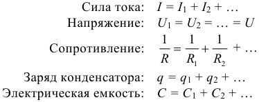
The formula for the total resistance of resistors connected in parallel is valid for any number of conductors. If the circuit is connected in parallel n identical resistances R, then the total resistance R 0 is found by the formula:
Electrical measuring instruments
To measure voltages and currents in DC electric circuits, special devices are used - voltmeters and ammeters.
Voltmeter designed to measure the potential difference applied to its terminals. It is connected in parallel with the section of the circuit where the potential difference is measured. Any voltmeter has some internal resistance R B. In order for the voltmeter not to introduce a noticeable redistribution of currents when connected to the measured circuit, its internal resistance must be large compared to the resistance of the section of the circuit to which it is connected.
Ammeter designed to measure the current in the circuit. The ammeter is connected in series to the break in the electrical circuit so that the entire measured current passes through it. The ammeter also has some internal resistance. R A. Unlike a voltmeter, the internal resistance of an ammeter must be small enough compared to the total resistance of the entire circuit.
EMF. Ohm's law for a complete circuit
For the existence of a direct current, it is necessary to have a device in an electric closed circuit capable of creating and maintaining potential differences in sections of the circuit due to the work of forces of non-electrostatic origin. Such devices are called DC sources... Forces of non-electrostatic origin acting on free charge carriers from the side of current sources are called outside forces.
The nature of external forces can be different. In galvanic cells or batteries, they arise as a result of electrochemical processes, in DC generators, external forces arise when the conductors move in a magnetic field. Under the action of external forces, electric charges move inside the current source against the forces of the electrostatic field, due to which a constant electric current can be maintained in a closed circuit.
When electric charges move along the DC circuit, external forces acting inside the current sources perform work. Physical quantity equal to the ratio of work A st of external forces when moving the charge q from the negative pole of the current source to the positive to the magnitude of this charge is called source electromotive force (EMF):
Thus, the EMF is determined by the work performed by external forces when moving a single positive charge. The electromotive force, like the potential difference, is measured in volts (V).
Ohm's law for a complete (closed) circuit: the current in a closed circuit is equal to the electromotive force of the source divided by the total (internal + external) resistance of the circuit:
Resistance r- internal (own) resistance of the current source (depends on the internal structure of the source). Resistance R- load resistance (external resistance of the circuit).
Voltage drop in external circuit at the same time equals (it is also called voltage at the source terminals):
![]()
It is important to understand and remember: EMF and internal resistance of the current source do not change when different loads are connected.
If the load resistance is zero (the source closes on itself) or much less than the source resistance, then the circuit will flow short-circuit current:
Short-circuit current is the maximum current that can be obtained from a given source with electromotive force ε and internal resistance r... For sources with low internal resistance, the short-circuit current can be very high and cause destruction of the electrical circuit or source. For example, lead-acid batteries used in automobiles can have short-circuit currents of several hundred amperes. Short circuits are especially dangerous in lighting networks powered by substations (thousands of amperes). To avoid the destructive effect of such high currents, fuses or special circuit breakers are included in the circuit.
Several sources of EMF in the circuit
If the chain contains several EMF connected in series, then:
1. With the correct (the positive pole of one source is connected to the negative of the other), the sources are connected, the total EMF of all sources and their internal resistance can be found by the formulas:
For example, such a connection of sources is carried out in remote controls, cameras and other household appliances powered by several batteries.
2. With an incorrect (sources are connected by the same poles) connection of sources, their total EMF and resistance is calculated by the formulas:
In both cases, the total impedance of the sources increases.
At parallel connection it makes sense to connect sources only with the same EMF, otherwise the sources will be discharged against each other. Thus, the total EMF will be the same as the EMF of each source, that is, with a parallel connection, we will not get a battery with a large EMF. At the same time, the internal resistance of the battery of sources decreases, which makes it possible to obtain a large current strength and power in the circuit:
This is the meaning of the parallel connection of sources. In any case, when solving problems, you first need to find the total EMF and total internal resistance of the resulting source, and then write Ohm's law for the complete circuit.
Work and power of the current. Joule-Lenz law
Work A electric current I flowing along a fixed conductor with resistance R, converted to warmth Q that stands out on the conductor. This work can be calculated using one of the formulas (taking into account Ohm's law, they all follow from each other):

The law of converting the work of current into heat was experimentally established independently of each other by J. Joule and E. Lenz and is called Joule-Lenz law. Electric current power equal to the ratio of the work current A to the time interval Δ t, for which this work was performed, so it can be calculated using the following formulas:

The work of electric current in SI, as usual, is expressed in joules (J), power - in watts (W).
Closed circuit energy balance
Consider now a complete DC circuit consisting of a source with electromotive force ε and internal resistance r and an external homogeneous area with resistance R... In this case, the net power or the power released in the external circuit:
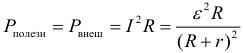
The maximum possible useful power of the source is achieved if R = r and is equal to:
If, when connected to the same current source of different resistance R 1 and R 2, equal powers are allocated to them, then the internal resistance of this current source can be found by the formula:
Power loss or power inside the current source:

Apparent power developed by the current source:
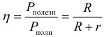
Current source efficiency:
Electrolysis
Electrolytes it is customary to call conductive media in which the flow of electric current is accompanied by the transfer of matter. The carriers of free charges in electrolytes are positively and negatively charged ions. Electrolytes include many molten metal-metalloid compounds, as well as some solids. However, the main representatives of electrolytes widely used in technology are aqueous solutions of inorganic acids, salts, and bases.
The passage of an electric current through the electrolyte is accompanied by the release of a substance at the electrodes. This phenomenon is called electrolysis.
Electric current in electrolytes is the movement of ions of both signs in opposite directions. Positive ions move towards the negative electrode ( cathode), negative ions - to the positive electrode ( anode). Ions of both signs appear in aqueous solutions of salts, acids and alkalis as a result of the splitting of some of the neutral molecules. This phenomenon is called electrolytic dissociation.
Electrolysis law was experimentally established by the English physicist M. Faraday in 1833. Faraday's law determines the amount of primary products released on the electrodes during electrolysis. So the mass m substance released at the electrode is directly proportional to the charge Q passed through the electrolyte:
![]()
The quantity k are called electrochemical equivalent... It can be calculated using the formula:
where: n- valence of a substance, N A is Avogadro's constant, M- molar mass of a substance, e- elementary charge. Sometimes the following notation for the Faraday constant is also introduced:
Electric current in gases and in vacuum
Electric current in gases
Under normal conditions, gases do not conduct electricity. This is due to the electrical neutrality of gas molecules and, consequently, the absence of carriers of electric charges. In order for the gas to become a conductor, one or more electrons must be removed from the molecules. Then there will be free charge carriers - electrons and positive ions. This process is called ionization of gases.
You can ionize gas molecules external influence - ionizer... Ionizers can be: a stream of light, X-rays, a stream of electrons, or α -particles. Gas molecules also ionize at high temperatures. Ionization leads to the appearance of free charge carriers in gases - electrons, positive ions, negative ions (an electron combined with a neutral molecule).
If an electric field is created in the space occupied by an ionized gas, then the carriers of electric charges will come into ordered motion - this is how an electric current arises in gases. If the ionizer stops working, then the gas becomes neutral again, since recombination- the formation of neutral atoms by ions and electrons.
Electric current in a vacuum
A vacuum is a degree of rarefaction of a gas at which one can neglect the collision between its molecules and assume that average length free path exceeds the linear dimensions of the vessel in which the gas is located.
Electric current in vacuum is called the conductivity of the interelectrode gap in a vacuum state. In this case, there are so few gas molecules that the processes of their ionization cannot provide such a number of electrons and ions that are necessary for ionization. The conductivity of the interelectrode gap in vacuum can be ensured only with the help of charged particles that arise due to emission phenomena at the electrodes.
- Back
- Forward
How to successfully prepare for a CT in physics and mathematics?
In order to successfully prepare for the CT in physics and mathematics, among other things, three important conditions must be met:
- Explore all topics and complete all tests and tasks given in the training materials on this site. To do this, you need nothing at all, namely: to devote three to four hours every day to preparing for the CT in physics and mathematics, studying theory and solving problems. The fact is that CT is an exam where it is not enough just to know physics or mathematics, you still need to be able to quickly and smoothly solve a large number of problems on different topics and of varying complexity. The latter can only be learned by solving thousands of problems.
- Learn all formulas and laws in physics, and formulas and methods in mathematics. In fact, it is also very simple to do this, there are only about 200 necessary formulas in physics, and even a little less in mathematics. In each of these subjects there are about a dozen standard methods for solving problems of the basic level of complexity, which are also quite possible to learn, and thus, completely automatically and without difficulty, at the right time, solve most of the CG. After that, you will only have to think about the most difficult tasks.
- Attend all three physics and mathematics rehearsal testing phases. Each RT can be visited twice to solve both options. Again, on the CT, in addition to the ability to quickly and efficiently solve problems, and knowledge of formulas and methods, it is also necessary to be able to properly plan the time, distribute forces, and most importantly, fill out the answer form correctly, without confusing either the numbers of answers and tasks, or your own surname. Also, during RT, it is important to get used to the style of posing questions in tasks, which on the CT may seem very unusual to an unprepared person.
Successful, diligent and responsible implementation of these three points will allow you to show excellent results at the CT, the maximum of what you are capable of.
Found a bug?
If you, as it seems to you, found an error in the training materials, please write about it by mail. You can also write about the error on the social network (). In the letter, indicate the subject (physics or mathematics), the title or number of the topic or test, the number of the problem, or the place in the text (page) where, in your opinion, there is an error. Also describe what the alleged error is. Your letter will not go unnoticed, the error will either be corrected, or you will be explained why it is not an error.
At school, I don't remember in which class they explained to me that the current flows from + to -. Those. if a light bulb is inserted between the terminals of the battery (there were such - KBS), then the current will pass through the positive terminal of the battery, then through the light bulb, it will light up and go to the battery through the negative terminal. After a couple of years, the physics teacher explained that the direction of the current from + to - is conditional. In fact, current is the movement of electric charges, from which only free electrons can move along the wire. Those. current flows from - to +.
A prerequisite the appearance of a current is the closure of the circuit. At that time, I was already mastering the 6P3S, connected to the anode of the output lamp of the broadcast receiver, and I had no doubts about this postulate. Especially after a couple of shocks with this current.
Days go by, add up to years. The first manifestations of senile insanity have gone, and apparently from this something I doubted about the acquired school knowledge.
Here we have a current source and a closed circuit with a load. He ran out, no matter from which terminal, rosy-cheeked, self-confident current and rushed to the load. I fought with her, because she didn't want to give herself up just like that and resisted, but the current did its job, though it gave the load part of its energy and, sweaty and slightly pale, ran to the second terminal of the source.
It seems to be a real picture, the law of conservation of energy is fulfilled, only to be tested - fantastic! The check is very simple: we insert it into the circuit before the load and after it according to the ammeter. And what do they show? And the fact that the magnitude of the current before and after intercourse with the load is the same!
Maybe the current is our liar and had no business with the load, so the ammeters show the same current? But no, if there was a light bulb as a load, then we saw a light. The waste of energy was undoubtedly! But what about the fact that the outgoing current is equal to the incoming?
Wonderful are your deeds, Lord!
An experience N 2.
We connect a wiring to each source terminal and try to determine the sign of the potential at their ends. Since the current is the movement of electrons, then due to the capacitance of the wiring and the potential difference between the terminal and the wire, electrons will run into the wire and at its end connected to the negative terminal, we will detect negative charges.
From the same definition of current, it follows that there will be no charges at the end of the conductor connected to the positive terminal. However, they show up there. Moreover, they are positive.
Stop! Positive ones don't run along the wire! Where did they come from there?
“But simply - they say knowledgeable people- The source gave part of the electrons to the wire and made up for the deficit by taking the same amount from another wire. Since there was a shortage of electrons in this wire, it was "charged" positively. The power source is a pump that pumps electrons. "
Seems like a normal explanation.
Stop. First, the number of free electrons is not infinite, for example, for a copper conductor, one free electron is about one and a half to two million atoms (1), and the magnitude of the current at short-circuit o-th! Secondly, if a load is connected to the wiring, and the current source is, in fact, a pump (why is it then called a source?), Then the energy of the outgoing current must be greater than the energy flowing in, since something must dissipate on the load. And the currents in the conductors are equal in magnitude. (The second time we do not mention the Creator in vain).
So how does the current flow ???
That from plus to minus, that from minus to plus - the same problem ...
To somehow understand it, it is logical to start with the definitions. In the conventional sense, the current is considered as traffic electric charges. This movement is caused by the electromotive force of the current source or the potential difference when electric charges move along the conductor from a charged object to an uncharged one. But we are not interested in the movement of charges, but in how they transfer energy.
Two models are generally accepted here. In the first, electrons (charge carriers) are considered as "balls" accelerated by emf or potential difference. That is, the more we accelerate them, the more energy they acquire. When meeting the load, the "balls" are decelerated, give it part of the energy, and naturally the number of "balls" passing through the conductor cross-section per unit of time decreases. In the second model, the charge is an energy formation. Passing through the load, some of the charges transfer energy to it and disappear. As a result, the magnitude of the currents in the branches of the circuit is not the same.
The contradiction between experience and the law of conservation of energy remains. Either in the "conservatory" something needs to be corrected, or we misunderstand something.
For those radio amateurs who are protesting about this logical reasoning, I will remind you of at least two facts known to them.
1. The VSWR value at the beginning of the feeder is less than at the input of the load supplied by it.
2. The amplitude of the standing waves of the current in LW or in a vibrator, supplied in the middle, with a length of several λ, decreases from the feeding point to the end of the wire.
An explanation for these facts is known: the loss of its energy by the current when the charges move along the conductor.
Let's pay attention to inconsistencies in some of the known provisions.
1. The speed of free electrons along the conductor does not coincide with the speed of current propagation in it.
2. The school electroscope can be charged with positive charges. If you put an uncharged electroscope next to it and connect them with a conductor, then a short-term charging current of the second electroscope arises in it. Those. POSITIVE charges flowed through the conductor. What is their bearer?
3. If two sources are switched on oppositely in the DC circuit, then each of them will be a load for the other, and the current in the circuit will have a difference value. In the case of alternating current, in the case of its meeting with the wave inhomogeneity of the circuit, a reflected current wave arises. This current wave moves towards the main and currents do not oppose each other... As if they do not notice each other.
We must honestly admit that we do not know what an electric current is!
In the generally accepted theory of electric current, it is indicated that before the current in the wire, an electric field propagates, without which the movement of charges is unthinkable. Those. in the above Experiment No. 2, a positive potential field spreads along one of the conductors, and a negative potential field on the other.
There is an assumption that the charges themselves are inertial free (2). It can be assumed that they are energy "bunches" of a longitudinal electric field and therefore, in the form of current waves, they can propagate from the terminal of the current source at the speed of the field in a given medium. If the conductors are shorted to the load, then each current wave will give it part of its energy, and the current in the “incoming” and “outgoing” branches of the circuit will be equal to the sum of the values of the currents flowing out of this terminal and flowing from the other terminal and passing through the load. Ammeters will show the same current! Thus, the law of conservation of energy with equal currents in the incoming and outgoing branches of the load is CONSERVED! And the current source lives up to its name: CURRENT OUT OF BOTH TERMINALS!
Fantastic? Not at all. There is practical evidence for this assumption, although the charges themselves are hypothetical.
Let's look at some of the processes in long feeder lines. To "reconcile" the speed of free electrons with the actual speed of propagation of energy in the line, it was assumed that the energy is carried by the TEM wave. For such a wave to be formed, at the beginning of the line, it is necessary, according to Poiting, that the magnetic field vector be perpendicular to the plane passing through the two wires of the line, and the electric field vector lies in this plane and is directed from one wire to another. The first condition is fulfilled with different directions of currents in adjacent wires. The "electronic pump" version successfully copes with this. But the second condition requires the presence of DIFFERENT POLAR CHARGES in the adjacent wires!
The "pump" is not able to fulfill this condition. But non-inertial charges are quite. It is enough to remember that the direction of current movement is taken conditionally ... If the movement of positive charges from the source terminal to the load is taken as the direction of current from the terminal, then the movement of negative charges from the terminal to the load is taken as the direction of current to the terminal. Those. when the current flows from both terminals, both conditions for the formation of a TEM wave are fulfilled. CONDITIONALITY OF THE CURRENT DIRECTION CREATES THE ILLUSION OF A CURRENT FLOWING FROM ONE TERMINAL AND ITS FLOWING INTO ANOTHER!
You cannot count how many delusions this illusion has created. But more on that later.
Another example confirming the assumption that current flows from both terminals is a line closed at the end, or more real example- loop, loop antenna. As is known from practice, at the end of the line or exactly in the middle of the perimeter of the frame, a current antinode is formed, the value of which, without taking into account losses in the line or antenna, is equal to twice the value of the incident current wave. Try to explain the origin of this antinode of the current without its outflow from both terminals? Will not work!
All of the above is not my invention. All this in the form of separate fragments is given in the textbooks. For example, the concept of current waves is found in B.G. Belotserkovsky. (3) in the XI section. And DP Linde (4) on page 17 gives a figure illustrating these same current waves with the movement of positive and negative charges in them. Only the authors of textbooks do not like to focus on the inconsistencies of individual provisions of the theory of electric current and, painting a rosy picture of the general knowledge of the universe, hide from the immature mind the idea that Science knows that it does not know anymore!
Summarize. Most likely, energy carriers, in addition to electrons and ions, are energy formations akin to an electric field. Alternating current in the form of current waves flows out of both terminals of the source and does not need, in contrast to the constant, in a galvanic circuit. Direct current can be thought of as alternating current with a very long period of oscillation. The peculiarities of the current, which are hardly noticeable at direct current, are very prominent at alternating current. Especially with an increase in its frequency.
As soon as the modelers were in the hands of radio amateurs, they immediately rushed to check the famous classical antennas and their systems with their help. And some of the results were shocking!
For example, it turned out that reactivity appears in the input resistance of a half-wave vibrator, fed into the gap of the web, when the feed point is shifted from the center. Where? After all, the vibrator has a resonant length! And the resonance - it resonates in Africa too! It is he, as many are sure, that ensures the effective operation of the antenna!
This misconception stems from the pattern of current flowing from one terminal of the source and flowing into the other, which assumes a closed circuit. If the circuit is not galvanically closed, then the role of the "contactor" is assigned to the capacitor, more precisely - to the displacement currents "flowing" in it. On this basis, the conviction was born that there are no antennas without a counterweight. Seek and find! And if you do not see the "gopher", then it certainly exists anyway!
For example, I.V. Goncharenko (5) argues that a half-wave vibrator powered from the end does not work without at least a small counterweight. In extreme cases, one of the wires of the power line acts as a counterweight. And if there is no feeder and the antenna is powered directly? Anyway, there must be a "gopher"!
For the J antenna, the counterweight is a quarter-wave stub. The RX3AKT antenna has the outer surface of the cable from which the loop is made. Well, most of all, the Fuchs Antenna enters into a stupor, in which the author by all known methods "untied" the vibrator from the power source.
An even more paradoxical situation has developed with the GP. It would seem that everything is clear, here is a vertical emitter, and here are counterweights that collect displacement currents. But curious radio amateurs, playing with the modeler, discovered (although this was known earlier, for example, when describing the operation of the square in the sources of the Dommann era) that coaxially located counterweights practically do not emit, therefore, they do not receive!
Well, we are too lazy to learn the basics of electrical engineering! A capacitor is a device for storing energy! We will not bother with whether or not there is a bias current, we note that in this device, in theory, not a single gram of energy from one plate through the dielectric is transferred to the other plate. There is no current through the capacitor, there are currents of its charge and discharge, which flow to and from the plate ALONG the same wire. And only to simplify the calculations of electrical circuits, the conduction current is assumed to be equal in magnitude to the displacement current "flowing" through the capacitor.
In the proposed current model, these inconsistencies do not arise. For example:
Dipole with offset of the feed point from the center
Direct (incident) current waves flow into the short and long parts of the vibrator from the source or from the feeder. Having reached the ends, they are reflected and flow to the feeding point, forming standing waves of current in superposition. But backward (reflected) waves do not arrive at the feeding point at the same time. Therefore, the magnitudes of the standing waves of the current at the terminals of the source (feeder) are generally not equal and do not coincide in phase. Therefore, the voltage and current at the source terminals are not in phase, which is a property of the reactive load. Countermeasure - galvanic isolation of the vibrator from the source, power line.
GP
The same picture as in the dipole. Currents flow into the vibrator and counterweights. Standing current waves form an alternating electric field between the vibrator and the counterweights. In the case of inequality of their lengths, reactivity appears in the input resistance.
End-fed half-wave vibrator
Suppose the vibrator is powered by a power line. The inflowing current and reflected from the unconnected end of the vibrator form a standing half-wave of the current. Since the currents lose part of their energy to radiate and overcome the active resistance of the wire, the current at the supply point is not zero. Standing current and voltage waves are also generated in the feeder wires. Since the vibrator emits part of the supplied energy, the energy of the standing waves in the wires of the line will be different. In the line wire connected to the vibrator, the amplitude of the standing wave current will be less, and in the unconnected line wire, it will be higher. To equalize the currents in the line, two methods are used. A buffer energy storage is placed between the antenna and the line - a resonator in the form of a parallel circuit or a quarter-wave stub. The second way is galvanic isolation using a transformer. Fuchs Antenna uses both methods.
The flow of current from both terminals of the source allows you to take a fresh look at the operation of the source itself. Any wire connected to the terminal carries current. If, as a rule, one wire is connected to the "positive" terminal: the antenna or the central core of the cable, then the radio station body and the ground wire are connected to the other. Those. the values of the incident waves of currents in the central core and the cable sheath are, in principle, not equal and measures should be taken to equalize them.
As a rule, the oscillatory system (CS) of a power amplifier of a radio station is a parallel connection of inductance and capacitance, the ends of which are connected to the corresponding output terminals. At each of them, two forces are added: the electromotive force, which sends charges to the load, and the force of attraction of the charges on the capacitor plates. Eds is, of course, stronger. But if the approximate equality of the values of the outgoing currents from both ends of the circuit is not ensured, then the number of charges on one of the plates will increase, and the force of their attraction will not allow the charges of the other plate to leave it. In this case, the COP will come out of resonance, and, in extreme cases, will refuse to supply the load. An interesting experience was described by E. Kuznetsov (RA 1AIT) (6). Working with a Fuchs antenna up to 5W, he found that when the antenna was connected to the rotary plates of a variable capacitor, it stopped working. When connected to the stator plates, the neon lamp, brought up to the capacitor body, shone brightly. Those. the capacity of the capacitor body was sufficient to accommodate the number of charges equal to the number of charges that went into the vibrator.
Realizing that this article will cause an ambiguous reaction, I will end with the words of the great poet: “Oh, how many wonderful discoveries the Spirit is preparing for enlightenment. And experience is the son of difficult mistakes. AND …"
Good luck to all. 73!
Literature.
A.A. Grishaev. Metals: non-stationary chemical bonds and two mechanisms for the transfer of electricity
When a person learned to create and use electric current, his quality of life increased dramatically. Now the importance of electricity continues to increase every year. In order to learn how to understand more complex issues related to electricity, you must first understand what an electric current is.
What is the current
The definition of electric current is its representation in the form of a directed flow of moving carriers-particles, charged positively or negatively. Charge carriers can be:
- electrons charged with a minus sign moving in metals;
- ions in liquids or gases;
- positively charged holes from moving electrons in semiconductors.

What is current is also determined by the presence of an electric field. Without it, a directed flow of charged particles will not arise.
Electric current conceptwould be incomplete without listing its manifestations:
- Any electric current is accompanied by a magnetic field;
- Conductors heat up as they pass;
- Electrolytes change the chemical composition.
Conductors and semiconductors
Electric current can exist only in a conductive medium, but the nature of its flow is different:
- Free electrons are present in metal conductors, which begin to move under the influence of an electric field. When the temperature rises, the resistance of the conductors also increases, since the heat increases the movement of atoms in a chaotic order, which interferes with free electrons;
- In a liquid medium formed by electrolytes, the resulting electric field causes the process of dissociation - the formation of cations and anions, which move towards the positive and negative poles (electrodes), depending on the sign of the charge. Heating the electrolyte leads to a decrease in resistance due to the more active decomposition of molecules;

Important! The electrolyte can be solid, but the nature of the current flow in it is identical to the liquid.
- A gaseous medium is also characterized by the presence of ions that move. Plasma is formed. Free electrons, which participate in directed motion, also arise from radiation;
- When creating an electric current in a vacuum, the electrons released at the negative electrode move to the positive one;
- In semiconductors, there are free electrons that break bonds from heating. In their places there are holes with a charge with a plus sign. Holes and electrons are capable of creating directional motion.
Non-conductive media are called dielectric.
Important! The direction of the current corresponds to the direction of motion of the particles-charge carriers with the plus sign.
Current type
- Constant. It is characterized by a constant quantitative value of the current and direction;
- Variable. Over time, it periodically changes its characteristics. It is subdivided into several varieties, depending on the parameter being changed. The predominantly quantitative value of the current and its directionality vary in a sinusoidal manner;
- Eddy currents. They occur when the magnetic flux undergoes changes. Form closed contours without moving between the poles. Eddy currents cause intense heat release, as a result, losses increase. In the cores of electromagnetic coils, they are limited by using a design of separate insulated plates instead of a solid one.

Electrical circuit characteristics
- Current strength. This is a quantitative measurement of the charge passing in a time unit over the cross section of the conductors. Charges are measured in coulombs (C), time unit is a second. The current strength is C / s. The resulting ratio was called ampere (A), in which the quantitative value of the current is measured. Measuring device - ammeter connected in series to the circuit of electrical connections;
- Power. The electric current in the conductor must overcome the resistance of the medium. The work expended to overcome it within a certain time period will be power. In this case, the transformation of electricity into other types of energy occurs - work is done. The power depends on the strength of the current, voltage. Their product will determine the active power. When multiplied by another time, electricity consumption is obtained - what the meter shows. Power can be measured in volt-amperes (VA, kVA, mVA) or in watts (W, kW, mW);
- Voltage. One of the three most important characteristics. For the current to flow, it is necessary to create a potential difference between two points of a closed circuit of electrical connections. Voltage is characterized by the work done by the electric field as a single charge carrier moves. According to the formula, the unit of voltage measurement is J / C, which corresponds to a volt (V). Measuring device - voltmeter, connected in parallel;
- Resistance. It characterizes the ability of conductors to transmit electric current. Determined by the conductor material, length and cross-sectional area. The measurement is in ohms (ohms).
Electric current laws
Electrical circuits are calculated using three main laws:
- Ohm's law. It was studied and formulated by a physicist from Germany at the beginning of the 19th century for direct current, then it was also applied for alternating current. It establishes the relationship between amperage, voltage and resistance. Almost any electrical circuit is calculated on the basis of Ohm's law. Basic formula: I = U / R, or the current is in direct proportional relationship with voltage and in reverse - with resistance;

- Faraday's law. Refers to electromagnetic induction... The appearance of inductive currents in conductors is caused by the influence of a magnetic flux that changes over time due to the induction of an EMF (electromotive force) in a closed circuit. The modulus of the induced EMF, measured in volts, is proportional to the rate at which the magnetic flux changes. Thanks to the law of induction, generators that generate electricity work;
- Joule-Lenz law. It is important in calculating the heating of conductors, which is used for the design and manufacture of heating, lighting devices, and other electrical equipment. The law allows you to determine the amount of heat released during the passage of an electric current:
where I is the strength of the flowing current, R is the resistance, t is the time.
Electricity in the atmosphere
An electric field can exist in the atmosphere, ionization processes occur. Although the nature of their occurrence is not completely clear, there are various explanatory hypotheses. The most popular is a capacitor, as an analogue for representing electricity in the atmosphere. Its plates can indicate the earth's surface and the ionosphere, between which the dielectric circulates - air.
Types of atmospheric electricity:
- Lightning discharges. Lightning with a visible glow and thunderclaps. Lightning voltage reaches hundreds of millions of volts at a current strength of 500,000 A;

- Lights of Saint Elmo. Corona discharge of electricity generated around wires, masts;
- Ball lightning. A ball-shaped discharge moving through the air;
- Polar Lights. The multicolored glow of the earth's ionosphere under the influence of charged particles penetrating from space.
Human use beneficial features electric current in all areas of life:
- lighting;
- signal transmission: telephone, radio, television, telegraph;
- electric transport: trains, electric cars, trams, trolleybuses;
- creating a comfortable microclimate: heating and air conditioning;
- Medical equipment;
- household use: electrical appliances;
- computers and mobile devices;
- industry: machine tools and equipment;
- electrolysis: obtaining aluminum, zinc, magnesium and other substances.

Danger of electric current
Direct contact with electric current without protective equipment is fatal to humans. Several types of influences are possible:
- thermal burn;
- electrolytic breakdown of blood and lymph with a change in its composition;
- convulsive muscle contractions can provoke fibrillation of the heart up to its complete stop, disrupt the work of the respiratory system.
Important! The current felt by a person starts from 1 mA, if the current is 25 mA, serious negative changes in the body are possible.
The most important characteristic of an electric current is that it can do useful work for a person: light a house, wash and dry clothes, cook dinner, heat a home. Now a significant place is occupied by its use in the transmission of information, although this does not require a large consumption of electricity.
Video
