Structural elements of the roof - what it consists of and what materials it is made of. Roof characteristics and construction: truss systems
The roof is the main element of any home. Today, for example, pitched roof options are especially popular. Such roofs are known to be the most reliable. If arranged correctly, they will last for several decades.
Today, there are many options. What kind of roof there will be depends on the size and characteristics of the house and, of course, the wishes of the owners. In any case, the structure of the rafter system is the most important element in the construction of the roof. Rafter structures, as practice shows, can be very different.
In this article, we suggest that you familiarize yourself with the most common options for roof structures, learn about their features, differences. In the photo presented in the article, you can see various rafter structures of pitched roofs.
The structure of the rafter system: its characteristics
Today, there are various types of truss structures. In any case, when constructing rafters, it is necessary to take into account the design features of the pitched roof and its load, including the mass of the snow cap. The structure of the rafters must be reliable and withstand all loads, otherwise the roof may collapse along with the building.
The design of the rafter system of a hipped roof is also relevant today. When building it, you need to remember that its loads will be many times greater than that of other types of roofs.
It is customary to distinguish permanent and temporary loads that are on. The first type includes the weight of the roof, the weight of structures and materials that were used in its construction. The second type includes loads that turn out to be external factors, for example, the weather. Any roof must withstand snow, strong winds. In addition, the roof is periodically repaired, so the roof structure must be able to withstand people being on it.
The rafter roof design can have many options. Thus, for each building, you can choose a roof of almost any shape.
Pitched roof shapes
Today, the most reliable and simple structures are single-slope and dual-slope roof options. The roof is also well known with four slopes. In this case, the roof can be, depending on the shape, hip, half-hip and hip. The hip roof has the shape of a trapezoid, half hip and has a triangular shape of various types.
The hipped roof version is the most common type. All slopes are triangular in shape, they rise in the form of a pyramid to the top, where they gather at one point.

There are also more complex forms of roofing structures. These include vaulted, mansard, conical, domed, pyramidal, broken, multi-gable and other forms of roofs (more: ""). The choice of the shape of the roof is influenced primarily by the features of the building itself, and secondly, by the family's budget. Usually, the more bizarre the shape of the roof, the more money its construction will require. The photo shows a variety of roof options.
What the rafter structure consists of
Installation of truss structures requires certain knowledge. First, the developer must know what the rafter includes. It, as a rule, consists of separate elements, which have their own characteristics and fastening rules. We propose to consider the drawing of a gable roof.
It must include the following points:
- Mauerlat is the main component of any roof structure. It is the foundation, the base of the roof and the support of future rafters. Mauerlat is a massive beams;
- The load-bearing roofing element is the rafter legs. Usually they are made of high-strength timber to be stable;
- In the upper part of the roof, there must be girders that are attached in the middle or between the ends of the rafter legs;
- A tightening or spacer can significantly increase the rigidity of the structure, with the help of them opposite sides of the Mauerlat are connected;
- Under the ridge, there must be a stand designed to support the legs of the rafters. She usually throws their weight over the puff;
- Braces are also required in the roof structure. They are sloped beams that run from the bottom of the rack to the middle of the rafter leg. That is, the struts support the rafter legs, evenly distribute their weight, and increase the rigidity of the structure. There are also longitudinal struts. They are between the legs of the rafters;
- If the structure needs to be located on two spans, then for this you need to use a bench, which will help to further strengthen the structure;
- The lathing is one of the main and complex elements of the roofing structure. It consists of rafter legs of a board or beams, on which layers of protection are usually laid, for example, heat, hydro and vapor barrier materials.
What are the roofing materials
The roof structure usually consists of planks or beams made from softwood. The thickness and hardness of the material can be very different. These indicators differ depending on the type of pitched roofs, the size of the building and the type of rafter system.
First, the builder should pay particular attention to the length of the rafters and the distance between their legs. The most optimal distance is 120 - 180 centimeters. The cross-section of the timber can be 8x10, 9x10 centimeters.
The rafters can be 4 meters long. In this case, the step should be 100 - 180 centimeters, and the section should be 8x16 or 9x18 centimeters.
The most optimal distance for 6-meter rafters is 100-140 centimeters. The section of the timber should be 8x20 or 10x20 centimeters.
If the roof is not very large, then there is no need to use struts. As for the stand, it is better to make it, in this case, the structure will be more durable.
On the market roofing materials For several years now, the expression “roofing pie” has taken root in Russia. However, many either do not understand what is behind this, or only know the basic versions of the "pie" designs without their varieties. Let's try to open this topic a little more broadly, referring to the standards adopted in Europe.
Usage and requirements
An elementary function of any roofing structure is protection against precipitation in the form of rain, snow, melt water and ice. The supporting structure of the roof must also withstand wind and snow loads, and in addition, the operational load arising from the movement of people along it during renovation works... The tasks of the roof include fire protection.
Simple use of the attic space requires protection from snow and dirt penetrating the roof. For more demanding use, protection against heat and cold and noise should also be provided. In the case of using the premises as a residential one, it is necessary to solve the problem of thermal insulation and preservation of comfortable humidity inside the premises. And finally, to all of the above, the urgent tasks of passive power generation and compliance with environmental requirements are added. Thus, in addition to climatic conditions, the choice of design is largely determined by the nature of its use.
Design principles
Today, there are technical capabilities to respond to the most diverse requirements for the roof, the whole complex constructive solutions that can be precisely matched with each other. The design principles are to implement the roofing tasks in each layer of the structure.
The current state of roofing technology can be defined by the following gradation:
- Single-layer structures that remove incoming moisture and dampness through only one layer of roofing.
- Two-layer structures, which involve the creation of an additional protective layer using an under-roof membrane or a lower protective roof.
- Constructions of three or more layers in which different insulating layers are separated by ventilation layers.
- Roofing sandwich panels / modular structures that integrate all the building-physical requirements in one element.
This approach - responding to different requirements by creating different layers - seems logical and appropriate, but it comes with some additional installation costs. The greater the number of layers increases the number of required junctions and, thus, the number of sources of possible defects. The modular design principle helps to solve these problems.
Let's consider the problem of ventilated and non-ventilated structures.
Terms and Definitions
Ventilated roofs - ventilated thermal insulation (roofs with two layers of ventilation)
Ventilated roofs are ventilation air layers that are located directly above the insulation. More precisely, these structures can be designated as "ventilated insulation".
Non-ventilated roofs - non-ventilated thermal insulation (single-layer ventilated roofs)
There is no ventilated layer directly above the thermal insulation. This means that a diffusion membrane or solid wood flooring with a diffusion membrane is laid on the surface of the insulation.
Temporary roof
A temporary roof (waterproofing layer) is installed before laying the roofing material and can protect the building from atmospheric precipitation for a long time until the roof is covered. After that, it forms one structural element with the roofing material.
Lower roof
The lower roof is understood as an independent waterproofing layer, which, even without the upper roof covering, is a waterproof roof.
Coating and insulation
Coating refers to the laying of elements with a free overlap, and insulation refers to waterproof bonding or welding of sheets. Thus, in the context of temporary and lower roofing, the concept of “temporary roof” and “temporary insulation” can be even more accurately distinguished, as well as the concepts of “lower deck” and “lower insulation”.
Ventilated - non-ventilated
The rules of the German Roofers Association recommend that roof spaces are designed as “ventilated structures”, ie. with ventilated (top) thermal insulation. However, it has been noticed that in roofing spaces exposed to various climatic influences, warm humid air moves from the heated part of the roof to colder areas of the roof structure that are not with sunny side, and there it gives off moisture (up to 100 g / m2 in 24 hours). This is especially true in cases where the waterproofing layer above the air gap is able to absorb only a small amount of moisture (e.g. smooth under-roofing films), so that the accumulated condensation water permeates the thermal insulation below.
Ventilated insulation
Since the fact described above was established, the time-tested ventilated design has been judged more critically. Ventilated insulation still has a right to exist due to the following unconditional advantages:
- Summer thermal insulation can be improved due to the removal of heated air masses through the lower ventilated duct.
- Incoming moisture, whether it is leaking water due to heavy rainfall, condensation arising from a sharp drop in temperature on the lower part of the flooring, or moisture seeping through the vapor barrier and insulating layer, from the internal space of the structure can be discharged due to the convective movement of air in the lower clearance.
- Ventilated structures contribute to reducing the negative consequences of errors and various kinds of incidents during work, especially when laying a vapor barrier and making its abutments.
- The boardwalk, which is often placed above the air layer, improves the soundproofing of the roof. However, the disadvantages of ventilated insulation should also be mentioned:
- Large heat loss due to air flow over open-cell mineral insulation, which requires a large thickness of thermal insulation material.
- In the case of inter-rafter insulation, the dependence of the height of the rafters on the sum of the heights of the insulating material and the air layer can lead to an excessive increase in the size of the rafters.
- The air gap can be considered "wet" due to the ingress of humid outside air into it, especially during the summer. In addition, harmful insects can enter the structure through the open lower gap, therefore it is necessary to use chemical protection of the tree.
- Providing adequate ventilation over large passages (windows, pipes, dormers), as well as in the area of the ridge and valley is associated with high labor costs.
- The inlets and outlets required to maintain ventilation in the bottom gap also require a lot of labor.
- With intensive ventilation of the lower gap, the risk of convective penetration of warm and, therefore, humid air from the interior into the insulation increases, which can lead to increased condensation of steam.
- Through the lower ventilation gap, a gradual clogging of the insulation with pollen, soot and dust occurs, which can contribute to increased moisture accumulation in the thermal insulation layer.
| Roof covering | Roofing with underlay film | Roofing with bottom roof | |
| Without insulation | |||
| Thermal insulation over the supporting structure | |||
| Thermal insulation between the rafter legs | |||
| Thermal insulation between the rafters and under the supporting structure | |||
| Thermal insulation under the supporting structure | |||
Cold (attic) roofs
Structures without thermal insulation are used in attics or buildings that are not intended for living (for example, warehouses). Roofing sheeting or subroofing can trap wind, dirt and blown snow. The lower roof is even more functional than the under-roofing film. When using it, it is permissible to deviate slightly to the smaller side from the standard indicators of the roof slope. In winter housing construction, the lower roof performs a valuable function when, due to weather conditions the main roof covering cannot be installed yet. In some climatic zones, the waterproofing properties of the wooden flooring, together with the waterproofing sheet lying on it, are already sufficient. With this design, the requirement for simple sound insulation can also be met.
Insulation over the supporting structure (insulation over the rafters)
This design has many advantages. The supporting structure is visible from the interior and is subject to only slight fluctuations in temperature and humidity. The thermal insulation layer passes without interruption over the entire area of the rafters, and its thickness can be selected independently of the supporting structure. Another advantage of this design is that the vapor barrier can be installed on the same level and continuously. The ventilation space is created by a counter-lattice of the required thickness. However, when using mineral wool as a rule, the installation of a supporting structure for a counter-lattice is required. These purlins interrupt the thermal insulation and must therefore be made of a material that is weakly heat conductive. The creation of an additional running layer, usually made of wood, is associated with certain material costs. With this design, it is optimal to use a durable insulation made of polyurethane or expanded polystyrene. Total height roof structure with insulation over the rafters is the largest of all existing. Special requirements are imposed on the vapor barrier layer: it must be non-slip and withstand high concentrated mechanical loads associated with the movement of roofers along the film during work. Therefore, leading manufacturers create special products for these roofs. Insulation between load-bearing elements (insulation between rafters) Despite the fact that the height of the entire structure in this case can be reduced, a fully functional structure will only be fully functional when the height of the rafter legs is significantly higher than required thickness thermal insulation. This is due to the fact that the rafter legs are potentially cold bridges. The larger the cross-section of the rafters and the smaller the pitch of their installation, the higher the thermal heterogeneity of the structure and the greater the heat loss. When using a two-layer ventilation scheme, the height of the rafter legs should be selected taking into account the required height of the ventilation gap between the insulation and the waterproofing film. It is also necessary to take into account the peculiarities of laying the film - with a sag or an interference fit. This design remains the most common and is suitable for both new construction and renovations. Its disadvantage is that the insulating layer is completely interrupted by the rafter legs, and there is also a high risk of convective transfer of moist air from the attic to the roof structure. The more intensive the ventilation in the lower gap, the higher the risk of humidification of the thermal insulation by vaporous moisture penetrating from a warm room.
Insulation between and under the supporting structure
This design is very reliable and easy to construct. As a rule, it is used in new construction, when the height of the truss structure is insufficient, and the required height of the entire roof structure must be as low as possible. An additional substructure is required to attach the vapor barrier and the inner finishing layer. The inner layer of insulation is usually placed between the frame bars / profiles interior decoration, overlapping the rafter legs and significantly reducing the risk of cold bridges formation.
If basalt wool slabs are used as an inner layer, then they also serve as additional fireproof insulation for the supporting rafter structure.
Insulation under the supporting structure
If the height of the existing supporting structure is too low, thermal insulation must be placed under the supporting structure. The insulation must be strong enough and suitable for fixing the vapor barrier and interior decoration, otherwise it will be interrupted by a frame substructure for finishing. The loss of volume in the interior must also be taken into account, since the entire structure is quite high. One of the significant disadvantages of this design is the location of all load-bearing elements in an external environment with variable temperature and humidity.
New requirements for the ventilation cross-section for ventilated roof structures (which do not require confirmation by calculations) are contained in the new DIN 4108 standard, as well as an indication of the maximum heat transfer resistance of the inner layer of 20% of the entire structure (insulation located in front of the vapor barrier layer from the side of the warm room ).
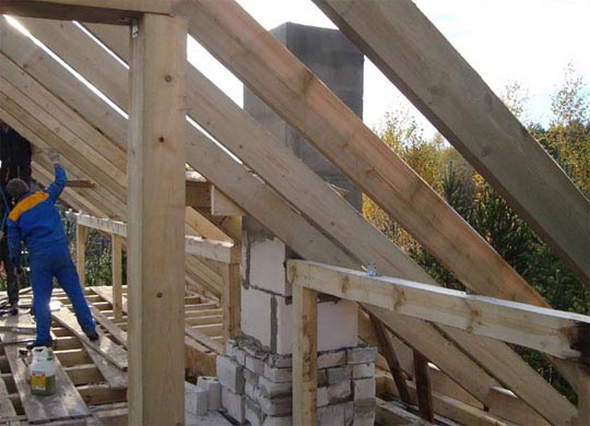
Non-ventilated insulation (complete thermal insulation of rafters / single layer ventilation scheme)
The disadvantages of ventilated structures correspond to the advantages of non-ventilated insulated structures:
- There is no convective heat transfer by the air flow above the insulating layer, which causes heat loss.
- In the case of using inter-rafter insulation, the entire height of the rafters can be used for the heat-insulating layer (i.e. increasing its thickness, which means reducing the cost of operating the house as a whole).
- Since the thermal insulation covered with a diffusion membrane is not exposed to moisture from the outside, the chemical protection of the wood can be dispensed with.
- There are no structural barriers for normal ventilation of complex roofs with valleys, abutments, dormer and dormer windows.
- There is no need for labor costs to create inlet and outlet (ventilation) openings along the valleys and abutments.
However, it is necessary to arrange one ventilation air layer under the roof covering. This layer serves to remove heat, melt water, as well as moisture seeping through the piece roofing material in the event of excessive rainfall. In addition, it helps to dry moist roof elements (insulation, rafters, flooring and battens). The drainage layer above the insulation must be diffusion-open with a maximum value of the equivalent thickness of the water vapor diffusion resistance Sd<= 0,2 м, чтобы влага, которая может находиться в теплоизоляции и деревянных элементах крыши, могла быть свободно выведена за счет диффузии.
However, non-ventilated insulation layers have disadvantages:
- As a rule, there is no solid wood flooring, which leads to a decrease in protection from external noise.
- It cannot be ruled out that the diffusion permeability of a waterproofing membrane located above the thermal insulation will decrease over time due to its contamination (this assumption has not been confirmed for multilayer membranes with a microporous closed structure, but it is quite possible when using single-layer membranes). Melted water and layers of ice temporarily accumulated on the membrane surface also increase the resistance to diffusion. If the vapor barrier under the insulation is defective or damaged, this can lead to typical wetting of the thermal insulation and damage to the entire structure.
- The high residual moisture content of the insulation and rafters can also lead to temporary formation of condensation in the thickness of the structure, but it will be removed from the roof after the first and long thaws in the spring.
- Finally, non-ventilated insulation cannot do without a vapor barrier with an equivalent thickness of the diffusion resistance of the air layer Sd> = 100 m. This means that all joints and abutments must be made without errors.
When implemented manually in the case of rafter insulation on a sloped roof, this can only be achieved with extremely careful design and the use of system accessories - adhesives, tapes and sealing pastes.
As a rule, structures with insulation between the supporting structure with one ventilation gap look as follows:
Thermal insulation between the truss structure
The creation and implementation of layers by hand has all the advantages and disadvantages listed above in the case of inter-rafter insulation with a non-ventilated heat-insulating layer. In working conditions where you have to work overhead and under an incline, it is easy to make mistakes. Added to this is the problem that sealed joints with existing structural elements are often performed by specialists from other industries. Therefore, the new DIN 4108 standard requires a certain ratio of the equivalent diffusion thickness of the air layer Sd for the layers outside and inside the thermal insulation. For certain structures (for example, non-ventilated roofs), the standard prescribes an Sd value> = 100 m for the inner layer.
To prevent the loss of the insulating effect if the insulation gets wet, it is possible to recommend the selection of a heat-insulating material with water-repellent properties. Indispensable components of such a design are a ventilated gap and a high diffusion openness of a windproof membrane laid on the insulation. With regard to the thermal resistance under the vapor barrier, the new DIN standard prescribes a maximum value of 20% of the value of the entire structure.
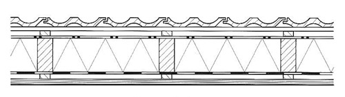
Thermal insulation over the supporting structure
The problems listed above speak in favor of a structure in which a layer of insulation is located above the supporting structure.
A construction with insulation over the rafter legs with one ventilation gap is as follows:
This design option contributes to the optimal installation of the vapor barrier and reduces the risk of errors in its implementation. In addition, the advantages listed for ventilated insulation layers apply here. There remain, however, the labor costs of securing the base of the flooring and the increased height of the structure, which only in rare cases imposes any restrictions.
Attic pitched roofs. The attic pitched roof consists of load-bearing structures and a roof. Between such a roof and the attic floor there is an attic used to accommodate ventilation ducts (boxes), pipe lines, etc. With significant slopes, attic spaces are often used for built-in rooms. The height of the attic in the lowest places, for example, near the outer walls, should be at least 0.4 m for the possibility of periodic inspection of the structures. In winter, heat and moisture penetrate into the attic through the attic floors from the premises of the upper floor. The warmer the attic and the more thermally conductive the roofing material, the more condensation (frost) will form. When the outside temperature rises, condensation will melt, causing rotting woodwork and corrosion metal elements... Humidification of the attic can also occur as a result of the penetration of moist air from the stairwells, in connection with which the density of the narthex of the doors and hatches leading to the attic becomes important. A very important and effective measure against humidifying the attic space is to ventilate it. To do this, arrange ventilation openings under the eaves (supply openings) and in the ridge (exhaust openings), as well as dormer windows. The load-bearing part consists of rafters, trusses, purlins, panels and other elements. The supporting structures of pitched roofs can be made of reinforced concrete, steel, wood in the form of rafters, building trusses and large panels. The choice of the roof structure depends on the size of the spans to be covered, the slope of the roof, as well as the requirements for durability, fire resistance and thermal properties (Fig. 3).
Rice. 3. :
1 - crossbar of the frame (beams, trusses); 2 - bearing element of the coating; 3 - vapor barrier; 4 - insulation; 5 - screed; 6 - roof; 7 - protective layer.
The most widespread are layered and hanging rafters. Raised rafters (Fig. 4) consist of rafter legs, struts and struts. They rest with the lower ends of the rafter legs on the rafter beams - Mauerlat, and with the upper ends on a horizontal bar called the upper ridge girder. The role of the Mauerlats is to provide comfortable support for the lower ends of the rafters. The upper purlin is supported by uprights that are mounted on internal supports. The distance between the racks carrying the ridge girders is taken equal to 3 ... 5 m.
Rice. 4. :
a-d - for pitched roofs; d, e - for gable roofs; g - the plan of the rafters; 1 - rafter leg; 2 - rack; 3 - brace; 4 - rafter bar; 5 - crossbar; 6 - spacer; 7 - top run; 8 - bed; 9 - diagonal leg; 10 - short rafter leg.
To increase the longitudinal rigidity of the rafter structures, longitudinal struts are installed, located at each rack. If the building has two rows of internal supports in the form of longitudinal capital walls or pillars, columns and other elements, then two longitudinal runs are laid. Inclined rafters are used in buildings with intermediate supports and spans up to 16 m in size.
V recent times prefabricated wooden layered rafters prefabricated at the factory became widespread. A set of such rafters consists of separate structural elements and has an abbreviated name - rafter board, rafter truss. Perhaps such a device of layered rafters made of precast concrete. Roof trusses are used when constructing roofs for buildings of considerable width that do not have internal supports. The construction truss consists of two rafter legs, connected by a tightening, which perceive the horizontal component of the forces transmitted to the support (thrust). With spans of trusses of 6 m or more, a crossbar is cut in, and with a span of up to 12 m, a headstock and struts are installed, which increase the rigidity and reduce the deflection of the rafter legs (Fig. 5).

Rice. 5. :
a - spans of trusses 6 m and more; b - the same, 12 m; 1 - crossbar; 2 - sleeper; 3 - brace; 4 - block; 5 - beams; 6 - tightening; 7 - grandmother; 8 - brace.
Roof trusses for low-rise civil and rural construction are made of beams and planks. Sometimes the elements that receive tensile forces in the lower chord or struts are made of steel. Such farms are called metal-wood. With four-pitched or more complex roof shapes, diagonal slant rafter legs are introduced, forming ramps of a triangular shape in plan, the so-called hips.
Inclined rafters are made of beams, boards and logs (see Fig. 4). The step of the rafters is taken depending on the material from which they are made, the type of roof and the section of the sheathing elements. When making rafters from beams 180 ... 200 mm thick, they are placed every 1.5 ... 2 m, and from plates and boards - every 1 ... 1.5 m.In buildings of considerable width, when the length of the rafter legs reaches 8 m, it is necessary to arrange intermediate supports on interior walls... On these walls, beds are laid, racks and struts are installed on them, and then a girder is installed on which the rafter legs rest.
At the intersection of roof slopes, layered rafters are made of diagonal and short rafter legs (see races 4, g). To protect the roof from being blown away by the wind, part of the rafter legs are tied to crutches driven into the outer walls with wire twists. All rafter mates are fastened with nails, bolts, staples. Reinforced concrete embankment systems consist of reinforced concrete panels supported at the top on a ridge reinforced concrete girder, and below on the outer walls of the building. The ridge girder is supported by pillars installed every 4 ... 6 m. Large reinforced concrete panels are used for pitched and gable roofs. Shed roofs are arranged on ribbed panels measuring 6.4x1.2 m, laid with a slope of 5%, gable roofs - with a slope of 7 ... 8%.
At present, complex multicomponent binders can be used for the manufacture of reinforced concrete bases. Before laying the roof, a cement or asphalt screed is arranged on the panels. In the absence of intermediate supports in small spans of buildings up to 12 m, hanging rafters are used (Fig. 6). They are made from the same materials as the layered rafters, that is, from beams, boards and logs. Hanging rafters consist of rafter legs and puffs. The upper ends of the rafter legs are connected with a slotted spike, and the lower ends are cut with a frontal cut into the tightening and fastened with bolts.
Rice. 6. :
1 - tightening; 2 - suspension, or headstock; 3 - rafter leg; 4 - suspended attic floor; 5 - brace; 6 - emergency bolt; 7 - nails; 8 - roof covering; 9 - two pads; 10 - bolts; 11 - bolt pins.
Attic roofs. Roofs without attic are subdivided into non-ventilated, partially ventilated and ventilated with outside air. Non-ventilated roofs are used in cases where moisture accumulation in the coating is excluded during operation. Such coatings can be performed with thermal insulation combined with the supporting structure. The main elements of the combined roof are flooring, insulation, vapor barrier and roof (Fig. 7).

Rice. 7. :
a, b - unventilated; в - ventilated; 1 - protective layer; 2 - rolled carpet; 3 - screed; 4 - thermal insulation; 5 - vapor barrier; 6 - ventilated channel; 7 - Basic structure; 8 - finishing layer.
The flooring is made of large-sized reinforced concrete slabs of various kinds... A vapor barrier layer in the form of one or two layers of roofing material or glassine on mastic is provided to protect the insulation from moisture vapor penetrating from the interior. Slab and bulk materials are used as insulation. thermal insulation materials... A leveling layer (screed) of cement mortar is made on top of the thermal insulation. A roof is arranged along the screed. It is made of rolled roofing materials in several layers. Stick them on cold or hot mastic. To protect the waterproofing carpet from damage, a protective layer is made in the form of sand or fine-grained gravel embedded in the top layer of mastic, or a layer of roofing material.
Non-ventilated roofs are assembled from solid or sandwich panels. Manufactured at the factory, such panels are sealed with a sticker on the upper surface of the waterproofing carpet, and below and along the contour of the panel - by applying a layer of paint vapor barrier. Partially ventilated roofs have pores or channels in the material of the panel, located in the upper thickness of the panel. Ventilated roofs have continuous air spaces that dry out the coating in winter and protect it from overheating sunbeams summer. The height of the air gap is 200 ... 240 mm. The combination roof structure consists of several layers of materials (see Fig. 7):
load-bearing element, for example reinforced concrete slab, which is trimmed from below to the ceiling of the upper floor;
vapor barrier from one or two layers of roofing material on mastic;
insulation - slabs of aerated concrete or backfill from expanded clay, slag and similar highly porous materials;
roofing made of rolled material, made of roofing felt, roofing, etc .;
a protective layer made of fine gravel or sieved slag embedded in the bitumen paint layer.
With an unventilated roof, a cement screed is arranged over the insulation. If the roof is not ventilated, the insulation screed is made of cement mortar. The roof railing consists of struts and struts and looks like a vertical steel grating. Racks and struts have bends at the bottom - legs with which they rest on the roof. The fences are fastened with wood grouses, driven into the roof lathing through the holes in the legs of the racks and struts. Parapets are arranged in the form of a solid stone wall with holes at the locations of the drainpipes.
Drainage systems. The drainage of water from the roofs of attic roofs (rain and thawed) can be disorganized and organized. With an unorganized drainage system, water flows from the roof along its entire length. Such drainage is allowed only in low-rise buildings, provided that the flowing water does not fall on the sidewalks. With an organized drainage system, the water flowing from the roof is drained through the gutters to the external drainpipes. There are three types of gutters: wall-mounted, suspended and remote (Fig. 8).
Rice. eight. :
a - wall gutter; b - reinforced concrete cornice-gutter; c - drain cornice with a suspended gutter (1 - roof; 2 - wall gutter; 3 - hook; 4 - funnel; 5 - drainpipe; 6 - suspended gutter; 7 - glued waterproofing; 8 - roofing steel; 9 - wood grouse; 10 - handrail post with a strut; 11 - enclosing rods, or strips); d - funnel of the internal drain (1 - funnel bowl; 2 - pressure ring; 3 - cover; 4 - fastening screw; 5 - fiberglass; 6 - asbestos-cement pipe; 7 - insulation; 8 - elastic gasket; 9 - flange; 10 - pressure screw).
Downpipes are made of roofing steel with a thickness of 0.5 ... 0.6 mm and consist of an upper funnel and a pipe made up of individual links and having bends at the top of the funnel and at the bottom of the elevation. Pipes are made with a diameter of 105, 140 and 215 mm. The diameter of the upper part of the funnel should be 2 ... 2.5 times the diameter of the pipe. Fastening of drainpipes to the walls is carried out using clamps located at a height of 1 ... 1.5 m and firmly embedded in the walls. With internal gutters on the roof, special water intake funnels are installed, connected to cast-iron risers passing inside the building and diverting water into an underground storm network or sewage system.
The cast iron funnel of the internal drain consists of a funnel bowl, a pressure ring, a cap or a roof, a fixing device (see Fig. 8). Water intake funnels are installed in the valleys. Pipes located inside the building drain atmospheric water into the storm sewer. The distance between the funnels depends on the length of the slope. The roof area per one funnel should not exceed 800 ... 1200 m 2. The necessary longitudinal slopes for water drainage to the funnels in the valleys are created due to the variable thickness of the layer of lightweight concrete laid in them. Longitudinal slope must be at least 1 °. The inlet funnels of internal drains are made of cast iron. The funnel consists of three main parts: a branch pipe that goes into the upper end and embedded in the cover structure, a body with holes for receiving water flowing from the roof and a cover or cap with holes. Each funnel is connected to a pipe (riser) with a diameter of at least 100 mm. In the places where the funnel is installed, holes of 400x400 mm are provided in the coating, into which a bowl-shaped cast-iron pan with an opening for the funnel pipe is inserted. When installing the branch pipe into the pallet, the areas between its walls and the funnel are poured with hot bitumen mastic. The inner surface of the pallet is pasted over with fiberglass or burlap soaked in bitumen, and the edges of the roof are inserted into it. The funnel body is installed in the branch pipe over the roof and in the lower part is also poured with bitumen.
© 2000 - 2002 Oleg V. site ™
