Scheme of the elements of the metal frame of an industrial building. Kirsanov N.M. Lecture text
Chapter 13. FRAMES, THEIR TYPES AND ELEMENTS
test questions
1. The main types of industrial buildings and the requirements for them.
2. Principles of space-planning solutions for one-story industrial buildings.
3. Principles of space-planning solutions for multi-storey industrial buildings.
The frame of one-story and multi-story industrial buildings consists of transverse frames, formed by columns and load-bearing structures of the coating (beams, trusses, arches, etc.), and longitudinal elements: foundation, crane and strapping beams, rafter structures, roof and floor slabs and ties (Fig. 12.3 and 12.4). If the supporting structures of the coatings are made in the form of spatial systems - vaults, domes, shells, folds, and others, then they are both longitudinal and transverse elements of the frame.
Frames of industrial buildings are assembled mainly from prefabricated reinforced concrete structures, steel and less often from monolithic reinforced concrete, wood and plastics.
When choosing a material, it is necessary to take into account the dimensions of the spans and the pitch of the columns, the height of the buildings, the magnitude and nature of the loads acting on the frame, the parameters of the air environment of production, the presence of aggressive factors, the requirements for fire resistance, durability, and technical and economic prerequisites.
The supporting frame is most often made entirely of reinforced concrete or steel and mixed. The device of a reinforced concrete frame in comparison with a steel one makes it possible to save up to 60% of steel. Frame elements are subject to force and non-force influences (Fig. 13.1). Force impacts arise from permanent and temporary loads. In this regard, the frame elements must meet the requirements of strength and stability.
Under the influence of non-force influences and the internal environment in the form of positive and negative temperatures, thermal shocks, liquid and vaporous moisture, air and chemicals contained in the air, the frame elements must meet the requirements of durability.
One-story industrial buildings with typical unified structures with an enlarged grid of columns can have structural schemes with or without truss structures (Fig. 13.2).
When choosing a frame made of steel elements, it is necessary to take into account the size of the spans, the operating mode of the cranes, the magnitude of the loads from the cranes and the coating, and other factors. The steel structures of the frame elements are used mainly in the workshops of factories that use heavy duty and continuous duty cranes. In this case, it is necessary to widely use lightweight mass-produced structures.
^ 13.1. frame industrial building
The frame of one-story and multi-story industrial buildings consists of transverse frames formed by columns and load-bearing roof structures (beams, trusses, arches, etc.), and longitudinal elements: foundation, crane and strapping beams, rafter structures, roof and floor slabs and ties (Fig. .12.3 and 12.4). If the supporting structures of the coatings are made in the form of spatial systems - vaults, domes, shells, folds, and others, then they are both longitudinal and transverse elements of the frame.
The frames of industrial buildings are mounted mainly from prefabricated reinforced concrete structures, steel, and less often from monolithic reinforced concrete, wood and plastics.
When choosing a material, it is necessary to take into account the dimensions of the spans and the pitch of the columns, the height of the buildings, the magnitude and nature of the loads acting on the frame, the parameters of the air environment of production, the presence of aggressive factors, the requirements for fire resistance, durability, and technical and economic prerequisites.
The supporting frame is most often made entirely of reinforced concrete or steel and mixed. The device of a reinforced concrete frame in comparison with a steel one makes it possible to save up to 60% of steel. Frame elements are subject to force and non-force influences (Fig. 13.1). Force impacts arise from permanent and temporary loads. In this regard, the frame elements must meet the requirements of strength and stability.
Under the influence of non-force influences and the internal environment in the form of positive and negative temperatures, thermal shocks, liquid and vaporous moisture, air and chemicals contained in the air, the frame elements must meet the requirements of durability.
One-story industrial buildings with typical unified structures with an enlarged grid of columns can have structural schemes with or without truss structures (Fig. 13.2).
When choosing a frame made of steel elements, it is necessary to take into account the size of the spans, the operating mode of the cranes, the magnitude of the loads from the cranes and the coating, and other factors. The steel structures of the frame elements are used mainly in the workshops of factories that use heavy duty and continuous duty cranes. In this case, it is necessary to widely use lightweight mass-produced structures.
Fig.13.1 - External influences on the frame elements:
1 - constant loads; 2 - live loads; 3 – internal air temperature; 4 - thermal shocks; 5 - liquid and vaporous moisture; 6 - aggressive chemicals; 7 - microorganisms; 8 - stray currents; 9 - sound
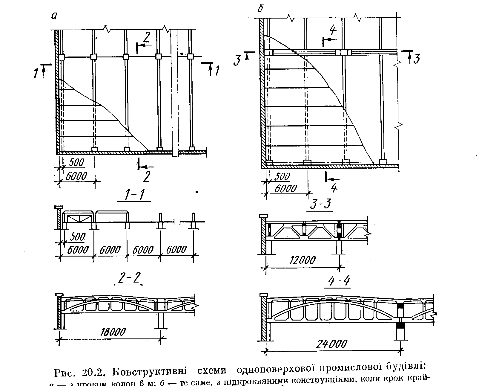
Fig.13.2 - Structural diagrams of a one-story industrial building:
a - with a step of columns of 6 m; b - the same, with rafter structures,
with a step of extreme columns 6 m
Frameworks multi-storey buildings they are also arranged from unified prefabricated reinforced concrete elements with beam or beamless ceilings (Fig. 13.3). Beam ceilings, as simpler and more versatile, are used more often. Beamless ceilings are used for large payloads and the need to obtain a smooth ceiling surface for hanging transport, interchanges in different directions of communications, as well as to improve the sanitary and hygienic qualities of the premises.

Fig.13.3 - Frames of multi-storey industrial buildings:
a - beam, when the crossbars are supported on the console of the columns (І - variant of the floors with the support of ribbed slabs on the shelf of the crossbars; II - the same, with the support of the plates on the top of the crossbars); b - beam, with non-cantilever support of crossbars (III - ceilings with ribbed slabs; IV - the same, with multi-hollow ones); c - beamless with over-column slabs located in two directions; g - the same, with over-column plates located in one direction; 1 - crossbar of the longitudinal frame; 2 - plumbing panel
^ 13.2. Foundations and foundation beams
According to the method of construction, the foundations are prefabricated and monolithic. Separate foundations with glass-type undercolumns are provided for the frame columns (Fig. 13.4), and the walls rest on foundation beams (Fig. 13.5).
Depending on the magnitude of the load on the columns, its cross section and the depth of laying the foundations, several standard sizes of foundations are used: the height of the foundation blocks is 1.5 and from 1.8 to 4.2 m with a gradation of 0.6 m; the dimensions of the base of the blocks in the plan are from 1.5x1.5 m and more with a module of 0.3 m; dimensions of the pedestal in terms of from 0.9x0.9 to 1.2x7.2 m with a module of 0.3 m. The depth of the glass is assumed to be 0.8; 0.9; 0.95 and 1.25 m, and the height of the steps - 0.3 and 0.45 m.
Prefabricated foundations can consist of one block (pillar with a glass) or be composite of a pillar and a support foundation slab. The device of prefabricated foundations is more economical than monolithic ones in terms of concrete consumption, cost and labor costs.
In order to reduce weight and reduce steel consumption, prefabricated ribbed or hollow foundations are used (Fig. 13.4).
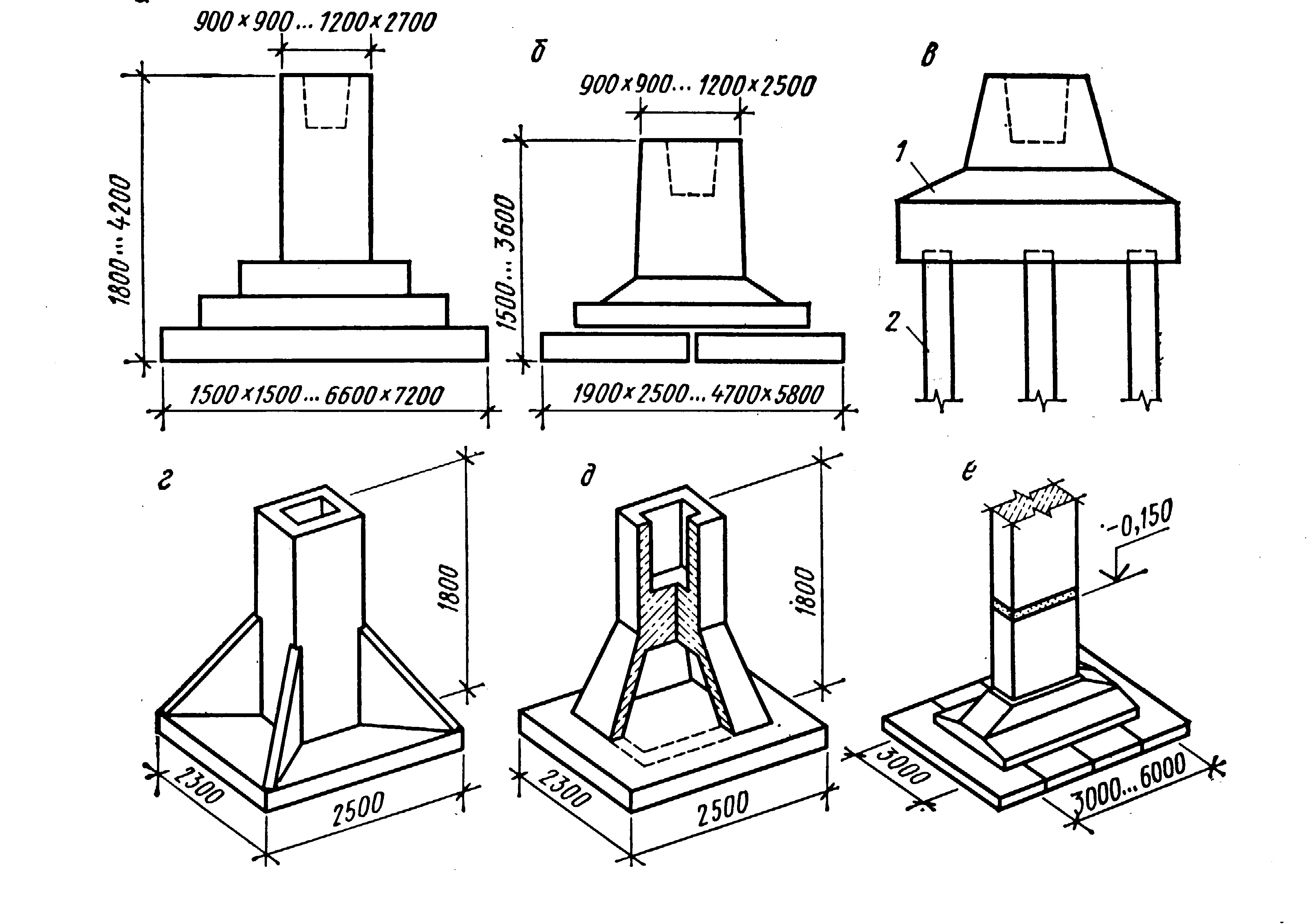
Fig.13.4 - Types of foundations for industrial buildings:
a - monolithic; b - prefabricated composite; in - pile; g - prefabricated ribbed; d - prefabricated hollow; e - with a hemp-type column; 1 - grillage; 2 - pile
Foundations with hemp-type pillars are arranged for reinforced concrete columns of large cross section or for steel columns (Fig. 13.4, e). The stump, which is an element of the column, is arranged during the work of the zero cycle. The stump with the foundation and the column with the stump are connected by welding of reinforcement outlets and concrete, which are injected into the seams.
Pile foundations are made in case of occurrence of weak soils near the surface of the earth and the presence ground water(Fig. 13.4, c). The head parts of the piles are connected with a monolithic or prefabricated reinforced concrete grillage, which is also a sub-column.
To reduce the size of the columns, the top of the foundations, regardless of the depth of the base, is recommended to be located at around 0.15 m, i.e. 15 cm below the mark of the finished floor of the workshop. They are installed on a grout of cement mortar 20 mm thick.
Hinged wall panels can be supported on a layer of concrete, transferring their mass directly to the under-columns.
1-2 layers of waterproofing material are laid along the foundation beams, and in order to prevent the deformation of the beams due to the possible heaving of soils, slag, coarse-grained sand or brick rubble are added from below and on the sides.
Bearing walls in frameless or incomplete frame buildings rest on strip foundations, which are recommended to be made from prefabricated elements. The principles of their device are similar civil buildings. This makes it possible to carry out the installation of columns with backfilled pits after the device for preparing under the floors and laying underground utilities, i.e. after the work of the zero cycle.
Columns with foundations are connected different ways. The most common rigid fastening with concrete.
The walls of frame buildings rest on foundation beams, which are laid between the under-columns of the foundations on special reinforced concrete columns or on the consoles of the columns. Foundation beams protect the floor from blowing in case of subsidence of the blind area. Reinforced concrete foundation beams (Fig. 13.5, a) with a column spacing of 6 m, depending on the size of the under-columns and support methods, have a length of 5.95 to 4.3 m, the cross section is T-shaped and trapezoidal.
The height of the beams for self-supporting walls made of bricks, small blocks and panels is taken 450 mm, and under hinged panels- 300 mm.
If the spacing of the columns is 12 m, mainly beams of trapezoidal section with a height of 400 and 600 mm and a length of 11.95-10.2 m are used. The beams are mounted so that their top is 30 mm below the floor level.

Fig.13.5 - Details of the foundations of the extreme row of columns:
a - types of foundation beams; b, c - details; 1 - sand; 2 - crushed stone preparation;
3 - asphalt or concrete pavement(blind area); 4 - waterproofing; 5 - column;
6 - slag or coarse sand; 7 - reinforced concrete columns; 8 - foundation beam
^ 13.3. Columns. Crane and strapping beams
Reinforced concrete and steel columns are used for the arrangement of frames of one-story and multi-story industrial buildings.
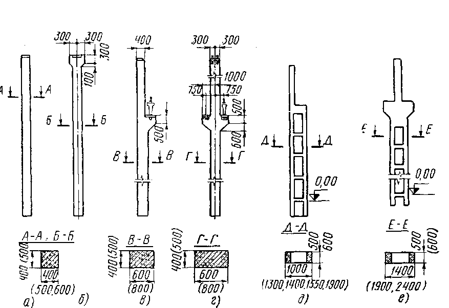
Reinforced concrete columns one-story industrial buildings (Fig. 13.6) can be with and without consoles (if there are no overhead cranes). According to their location in the plan, they are divided into columns of middle and extreme rows.
Depending on the cross-section of the column, there are rectangular, T-section and two-branch. The dimensions of the cross section depend on the magnitude of the acting loads. The following unified column section sizes are used: 400x400, 400x600, 400x800, 500x500, 500x600 and 500x800 mm - for rectangular; 400x600, 400x800 mm - for tee and 400x1000, 500x1300, 500x1400, 500x1500, 600x1400, 600x1900 and 600x2400 mm for two-branch. Columns may consist of several parts that are assembled at the construction site.
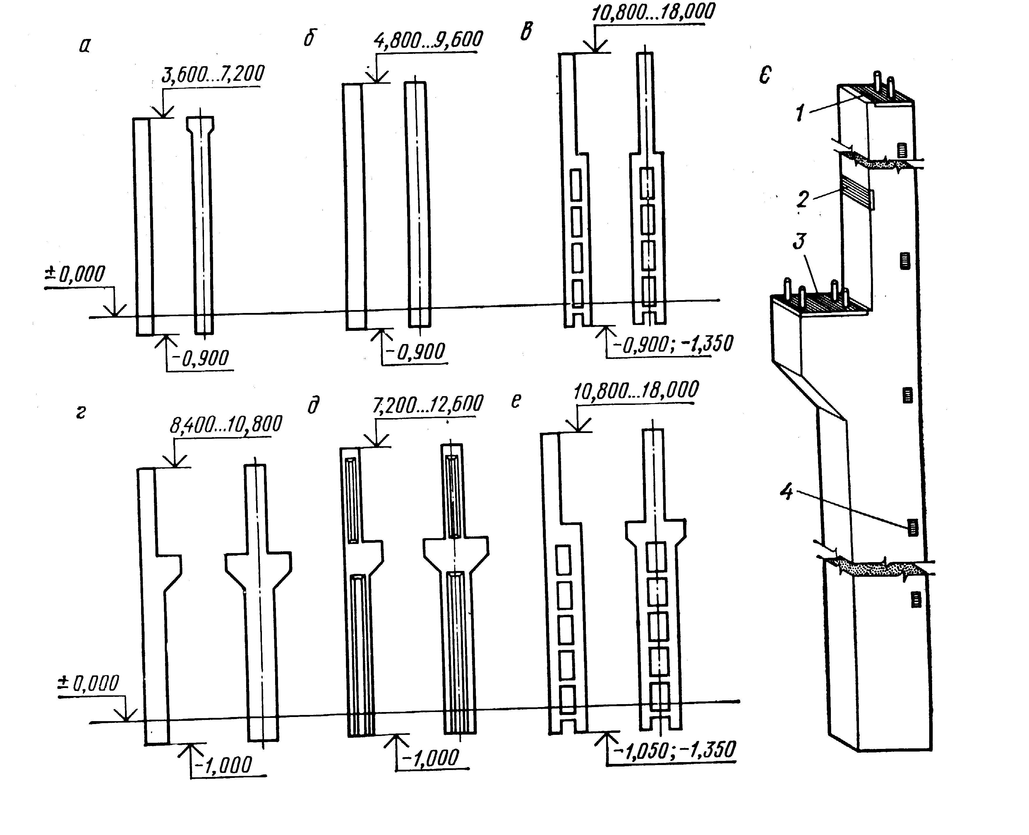
Fig.13.6 - The main types of reinforced concrete columns
one-story industrial buildings:
a - rectangular section for buildings without overhead cranes at a step of 6 m; b - the same, with a step of 12 m; c - two-branch for buildings without overhead cranes; g - rectangular section for buildings with overhead cranes; e - the same, two-tee section; e - two-branch for buildings with overhead cranes; e - general view of the column; 1 - backfill part for fastening the supporting structure of the coating; 2, 3 - the same, crane beam; 4 - the same, wall panels
Columns with consoles consist of over-crane and under-crane branches. The cross-section of overhead branches is most often square or rectangular: 400x400 or 500x500 mm.
In addition to the main columns, half-timbered columns are used for the construction of half-timbered houses. They are installed along the building with a spacing of the outermost columns of 12 m and a length of wall panels of 6 m, as well as at the ends of buildings.
For the construction of frames of multi-storey buildings, reinforced concrete columns are used one, two and three floors high. The section of the columns is 400x400 and 400x600 mm (Fig. 13.7). The connection of crossbars with columns can be cantilevered and non-cantilevered. The joints of the columns are arranged 600-1000 mm above the ceiling.

Fig.13.7 - Types of reinforced concrete columns of multi-storey industrial buildings
when operating crossbars on the console of columns
^ steel columns one-story buildings can have a constant height and a variable cross section. In turn, columns with a variable section can have a crane runway of a solid and through section (Fig. 13.8). Through columns are divided into columns with branches connected by ties, and separate columns, which consist of independently operating tent and crane branches (Fig. 13.8, e). Columns of constant section are used in the case of using cranes with a lifting capacity of up to 20 tons and a building height of up to 9.6 m.
In the case when the columns mainly work on central compression, solid section columns are used. For the manufacture of solid columns, a wide-shelf rolled or solid I-beam is used, and for through columns, I-beams, channels and corners can be used.
Separate columns are arranged in buildings with heavy overhead cranes (125 tons and more). At the bottom of the columns for connection with the foundations, steel bases (shoes) are provided. The bases are fixed to the foundations with anchor bolts, which are laid in the foundation during their manufacture. The lower supporting part of the column, together with the base, is covered with concrete.
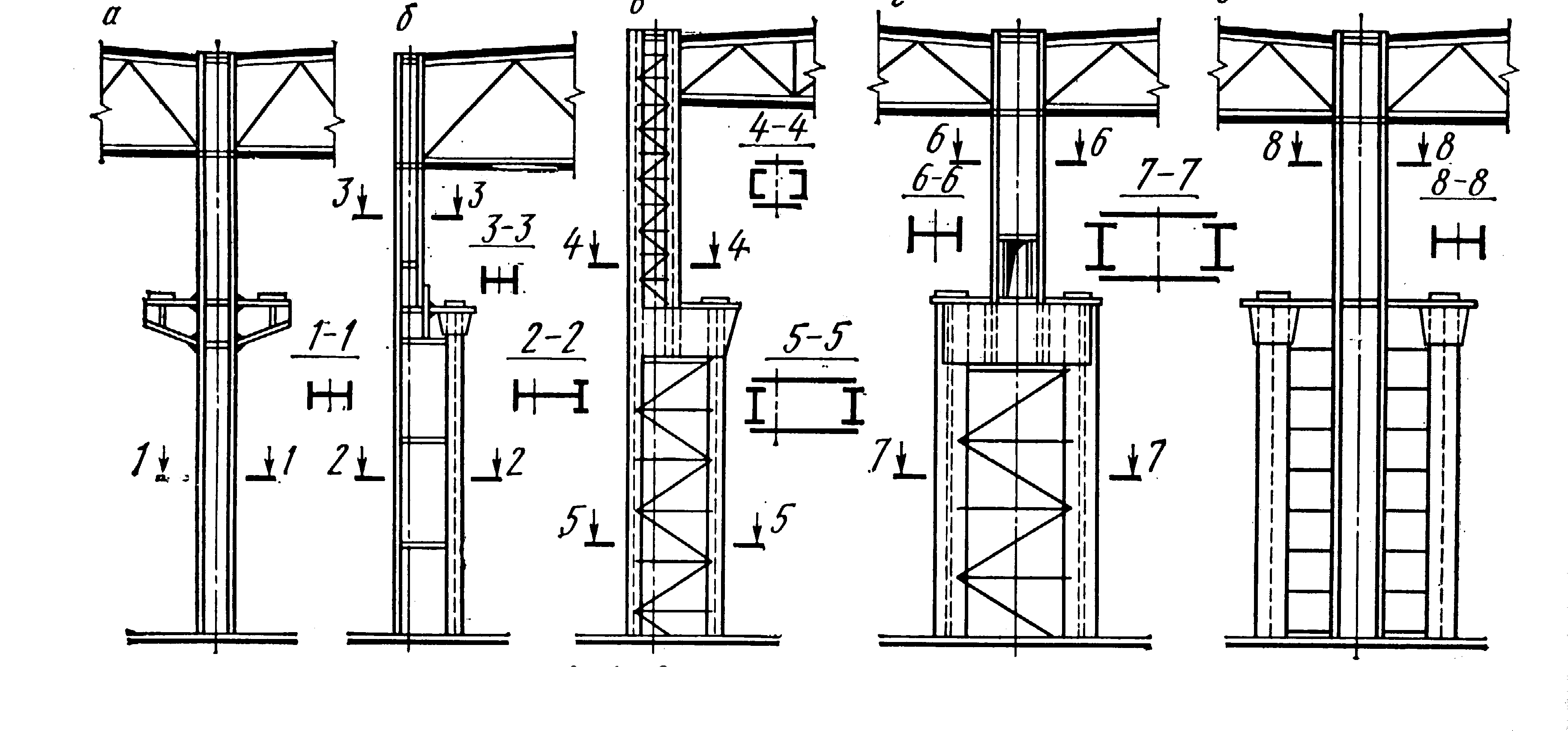
Fig.13.8 - The main types of steel columns:
a - constant cross section; b-d - variable section; d - separate
Rigidity and stability of buildings are achieved by installing a system of vertical and horizontal connections. So, in order to reduce and redistribute the forces that arise in the frame elements from temperature and other influences, the building is divided into temperature blocks and vertical connections between the columns are arranged in the middle of each block: with a column spacing of 6 m - cross; with a column spacing of 12 m - portal (Fig. 13.9). Connections are made from corners or channels and welded to the embedded parts of the columns.
To ensure the operation of overhead cranes, crane beams are mounted on the console of the columns, on which rails are laid. Crane beams also provide additional spatial rigidity of the building. They can be reinforced concrete and steel.
^ Reinforced concrete crane beams they are used with a column spacing of 6 and 12 m, but relatively rarely, since they have a significant mass, consumption of concrete and reinforcement. Beams can have a T-section (for a length of 6 m) and a two-T section with wall thickening only on supports.
Reinforced concrete crane beams are fixed to the columns by welding embedded parts and anchor bolts. After careful installation and alignment, the nuts on the anchor bolts are welded. The rails are attached to the beams with presser feet, which are placed every 750 mm. At the ends of the crane runways, steel stops are installed - limiters, equipped with buffer shock absorbers made of wooden beams.

Fig.13.9 - Vertical connections between the columns and the device of the expansion joint:
1 - cross connection; 2 - portal communication
More efficient than reinforced concrete are steel crane beams, which are divided into split and non-cut. They are easier to manufacture and install. According to the type of section, crane beams can be through (lattice) and solid.
The height of the beams is determined by calculation, it can be from 650 to 2050 mm with a gradation of dimensions through 200 mm.
Fastening rails to beams can be fixed and movable. The fixed fastening is carried out by welding the rail to the upper flange of the beam with cranes with a lifting capacity of up to 30 tons. The movable fastening, which is used most often, is made using brackets and presser feet.
If bricks or small blocks are used as materials for the walls, then reinforced concrete beams are used to support them, as well as in places where the heights of adjacent spans differ (Fig. 13.10, a). They are usually arranged over window openings or glazing strips.
Strapping beams with a length of 5950 mm have a section height of 585 mm and a width of 200, 250 and 380 mm. They are installed on supporting steel tables and attached to the columns using steel strips welded to the embedded elements (Fig. 13.10, b).

Fig.13.10 - Strapping beams:
a - general view; b - attachment point to the column; 1 - steel support table;
2 - steel bar
^ 13.4. Bearing structures of the coating
The load-bearing structures of the pavement, which are the most important constructive element buildings are taken depending on the size of the span, the nature and values of the existing loads, the type of lifting equipment, the nature of production and other factors.
By the nature of the work, they are planar and spatial. According to the material of construction, the coatings are divided into reinforced concrete, metal, wood and combined. Due to the nature of the work, these structures must be strong, stable, durable, architectural and artistic and economical. Therefore, when choosing the bearing structures of the coating, a thorough technical and economic analysis of several options is carried out. Thus, reinforced concrete structures are fire-resistant, durable and often more economical than steel structures. Steel, on the other hand, have a relatively small mass, are easy to manufacture and install, and have a high degree of assembly. Wooden structures are distinguished by their lightness, relatively low cost and, with appropriate protection, acceptable fire resistance and durability. Combined designs, which consist of several types of materials, are quite effective. At the same time, it is important that each material works in the conditions that are most favorable for it. Below are the main types of load-bearing structures of coatings.
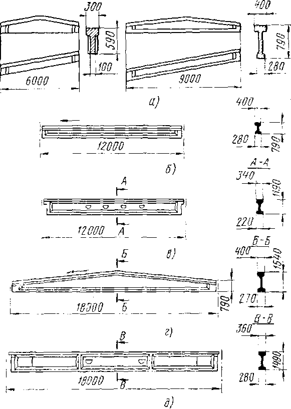
^ Reinforced concrete beams (Fig. 13.11) are used for spans up to 18 m. They can be single- and dual-slope. For their manufacture, prestressed reinforcement is used. On the upper belt of the beams, embedded parts are provided for fastening the covering panels or girders. The beams are attached to the columns by welding embedded parts (Fig. 13.11, e).
More efficient than beams reinforced concrete trusses, which are used in buildings with a span of 18, 24, 30 and 36 m (Fig. 13.12). They can be segmented, arched with parallel belts, triangular, etc. A system of racks and braces is placed between the lower and upper belts of trusses. The lattice of trusses is provided in such a way that floor slabs with a width of 1.5 and 3.0 m rest on trusses in the nodes of racks and braces.
Segmented bezraskosny reinforced concrete trusses with a span of 18 and 24 m are widely used. To reduce the slope of the coating for multi-span buildings, special racks (pillars) are provided on the upper belt of such trusses, on which the coating panels rest.
The trusses are fastened to the columns with bolts and welding of embedded elements.
With a pitch of trusses and beams of 6 m and a pitch of columns of the middle rows of 12 m, reinforced concrete trusses and beams are used.
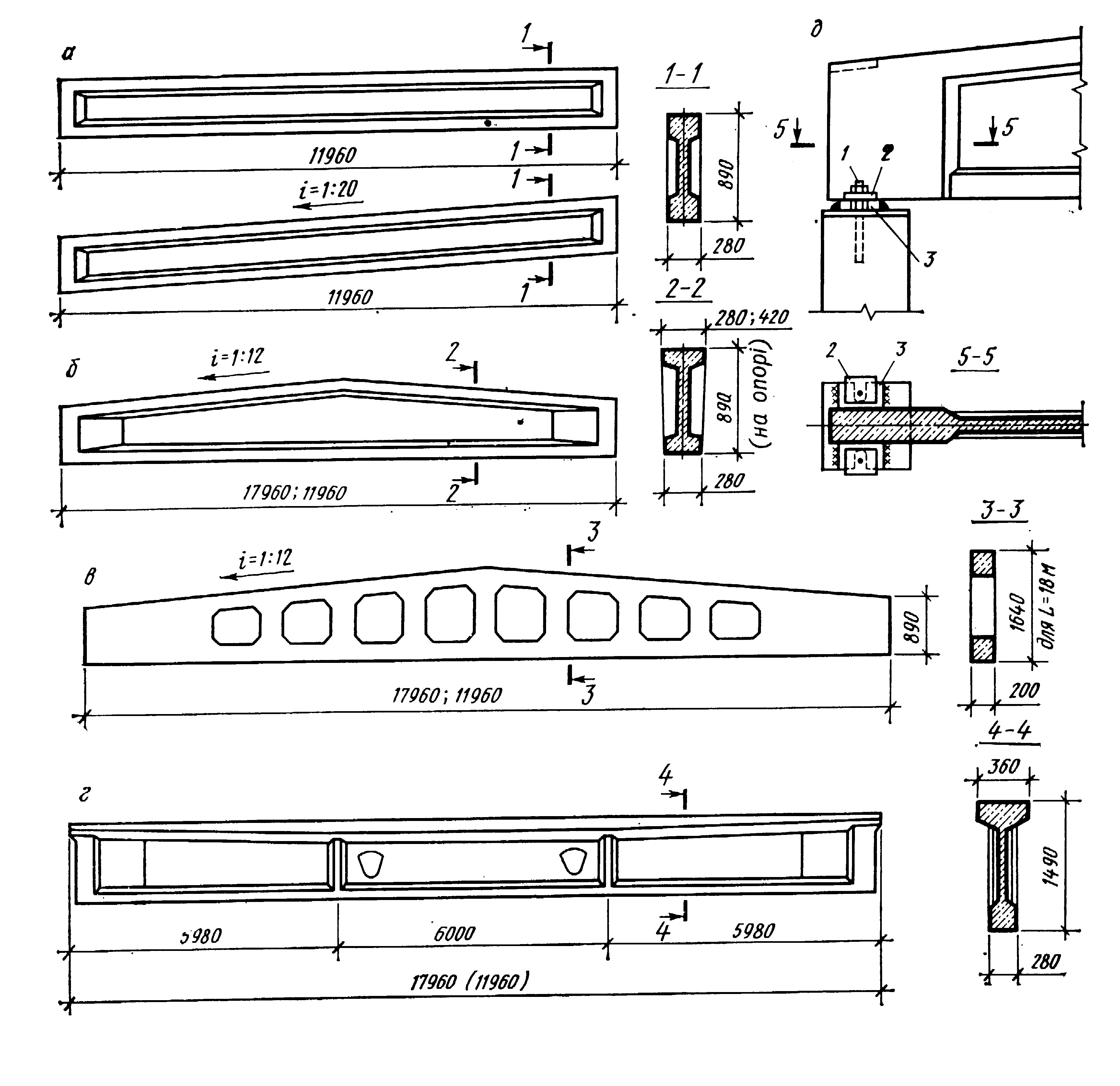
Fig.13.11 - Reinforced concrete roof beams:
a, d - single-pitched and flat two-tee sections; b - the same for multi-pitched coatings; c - lattice for multi-slope coatings; d - node supporting the beam on the column;
1 - anchor bolt; 2 - washer; 3 - base plate
Sufficiently effective bearing structures of the coatings are steel roof truss trusses (Fig. 13.13). Roof trusses are used for spans of 18, 24, 30, 36 m or more at a step of 6, 12 m.
Belts and truss lattice are constructed from corners or pipes and connected by welding using sheet steel gussets. The sections of the shelves of the belts, racks and braces are taken according to the calculation.

Fig.13.12 - Reinforced concrete roof trusses:
a - segmental; b - arched bezraskosnaya; in - with parallel belts; g - trapezoidal; e - a fragment of a section of the building covering with the use of truss trusses
For multi-storey industrial buildings, beam and beamless ceilings are used. Floor beams (crossbars) are made of concrete grades 200-400 with coordination spans of 6 and 9 m with a unified section height of 0.8 m. Beams can have a rectangular and tee section (Fig. 13.14). Rectangular crossbars are made under heavy loads. The connection with the column is carried out by supporting the crossbar on the console of the column.

Fig.13.13 - Steel roof trusses:
a - the main types of farms; b - node of support on the truss column with parallel belts with "zero" binding; c - the same, polygonal with a binding of 250 and 500 mm; d - the same, triangular with "zero" binding; 1 - support rack; 2 - column; 3 - fachwerk crossbar
For multi-storey buildings with a prefabricated beamless frame with a grid of columns 6x6 m, flat floor slabs of a solid section (above-column and span) with a thickness of 150 or 180 mm are used. Above-column slabs are installed with protrusions into the sockets of the capital, provided along its perimeter, with the formation of reinforced concrete dowels after embedding.
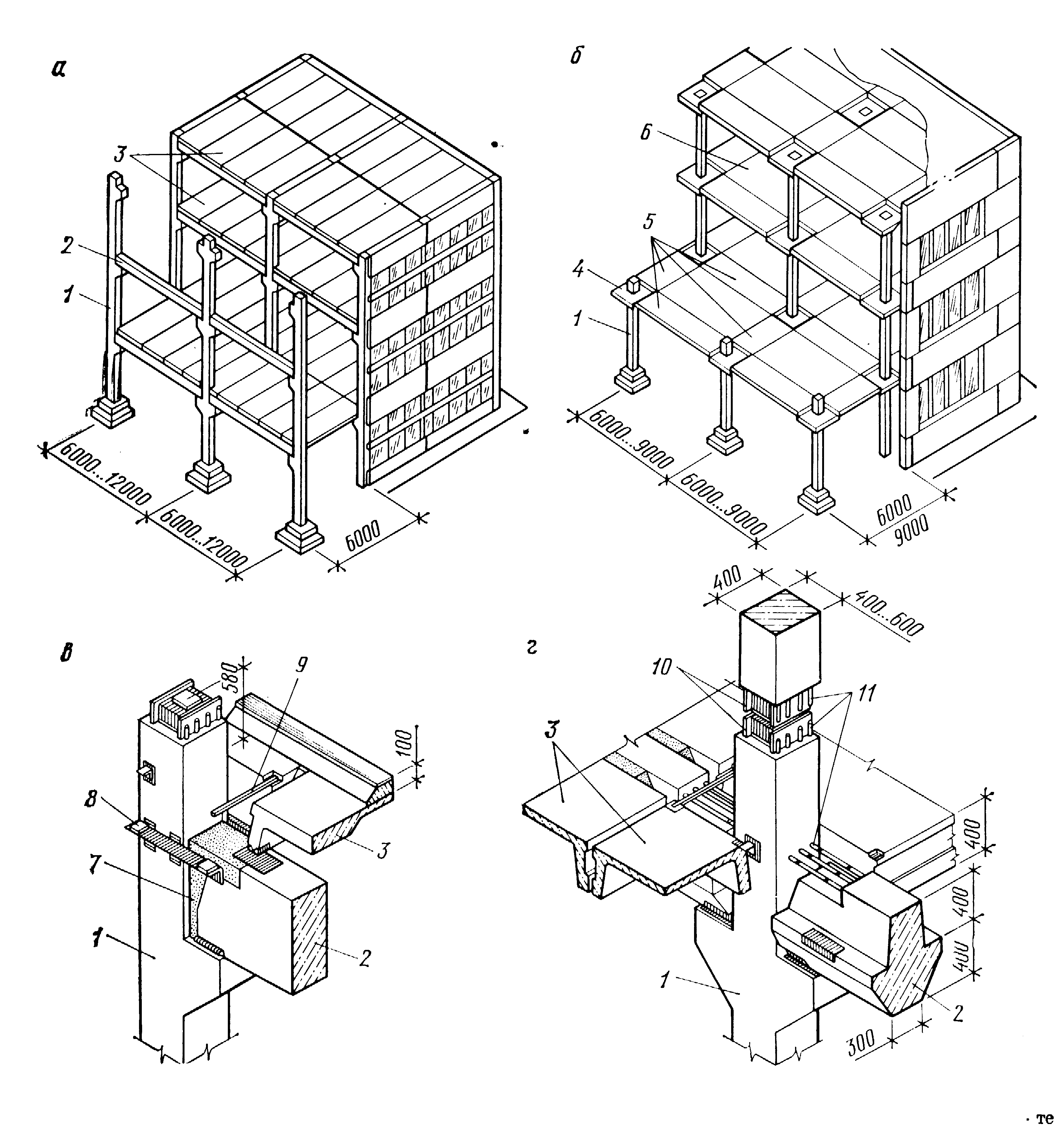
Fig.13.14. – Floor structures of multi-storey industrial buildings:
a - beam ceiling; b - beamless ceiling; in - support of a crossbar of rectangular section; g - the same, tee section; 1 - column; 2 - crossbar; 3 - floor panel; 4 - capital; 5 - over-column plates; 6 - span plate; 7 - concrete; 8 - shelf for supporting the floor slab; 9 - butt plate; 10 - steel head; 11 - releases of fittings
Large-span and spatial structures of coatings are used for the arrangement of premises of considerable size. Coverings in large-span buildings are planar, spatial and hanging.
^ Large-span surface coatings are reinforced concrete and steel trusses (Fig. 13.15). Reinforced concrete trusses with a span of up to 96 m are made of M500 concrete with a prestressed lower chord. Prefabricated and monolithic frames and arches with different spans are also used.
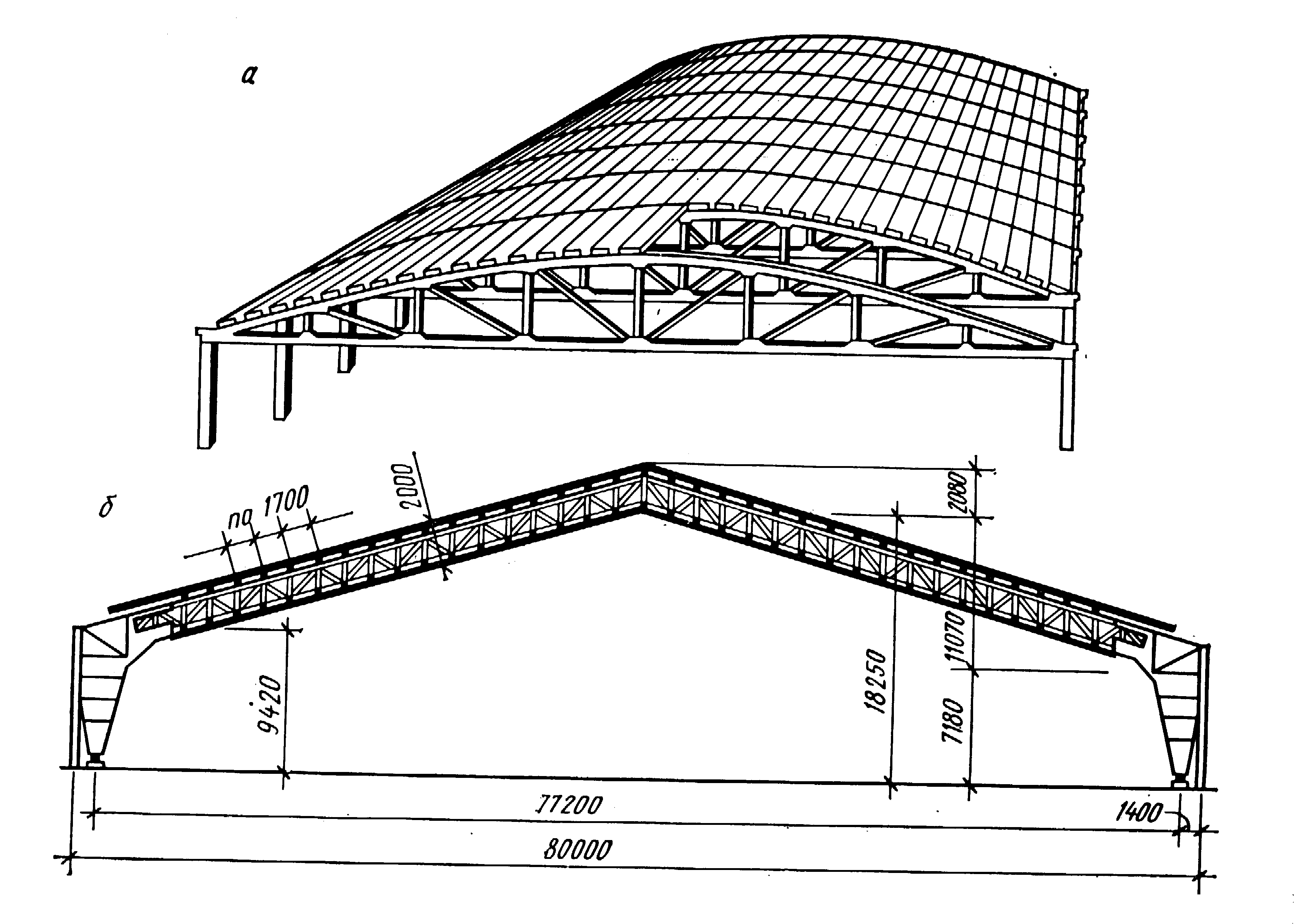
Fig.13.15 - Long-span flat coatings:
a - with reinforced concrete trusses with a span of 96 m;
b - with metal frames with a span of 80 m
Spatial coatings are made of planar elements, monolithically interconnected and working as an integral structure, or in the form of shells (Fig. 13.16). The shells that can cover large spans have an insignificant thickness of 30-100 mm, since the concrete in this case works mainly in compression.
The shells can be cylindrical, domed, paraboloid, etc. The coating of long cylindrical shells used with a grid of columns of 12x24 m or more has good performance.
satisfied also hanging covers, which work in tension (Fig. 13.17). Hanging structures are divided into cable-stayed and actually hanging.
The load-bearing elements in cable-stayed roofs are cables and cable-stayed rectilinear elements. As flooring, aluminum-plastic panels, fiberglass box flooring and honeycomb panels are used. Cable-stayed roofs can span 100 m or more.
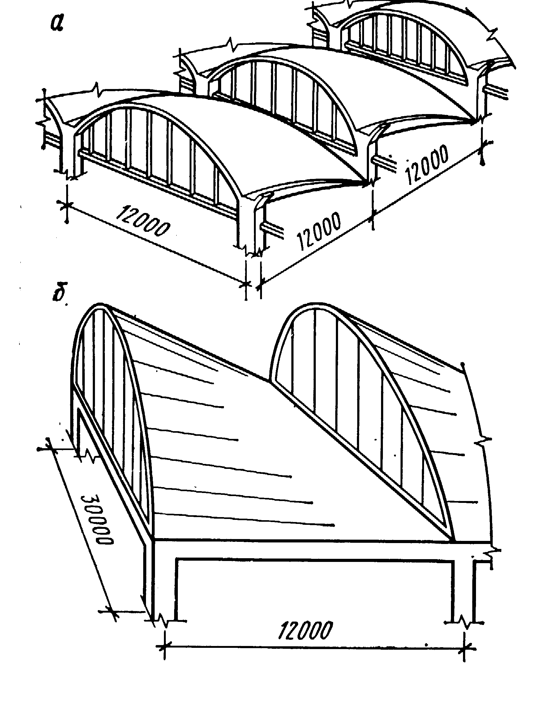
Fig.13.16 - Examples of coatings in the form of shells:
a - shed with diaphragms in the form of reinforced concrete arches; b - the same, in the form of steel trusses of a curvilinear shape

Fig.13.17 - Hanging covers:
a - one-belt span 12 + 78 + 12 m; b - double belt span 9 + 50 + 9 m
In actually hanging roofs, the supporting structures are membranes and flexible threads, curvilinearly outlined under the action of the load applied to them.
AT industrial construction Pneumatic constructions are also widely used. The principle of their erection is based on the fact that atmospheric air is injected into the inner closed space of soft shells, which stretches the shell, giving it a given shape, stability and bearing capacity. The material of the shells of these buildings must be airtight, elastic, strong, light, durable and reliable in operation.
test questions
Definition of the building frame and the main elements of the frames of one-story and multi-story industrial buildings.
Peculiarities constructive solutions foundations of industrial buildings.
Foundation beams.
Constructive solutions for columns of industrial buildings.
Crane beams, their types and design solutions.
In what cases are strapping beams used?
Reinforced concrete bearing structures of coatings.
Metal load-bearing structures of coatings.
Large-span and spatial coatings.
Steel frames of one-story industrial buildings
Steel frames are used in the construction of large workshops with large spans, mainly in heavy industry and have a structural scheme similar to reinforced concrete. At present, our industry has mastered economical types of rolled steel, the use of which in industrial construction helps to reduce the mass of buildings and ensures the industrialization of construction.
Steel frames are especially rational for industrial buildings erected in hard-to-reach areas or at a significant distance of construction objects from production bases, which is determined by the relatively small mass of steel structures.
It should be noted that the use of steel structures allows to reduce the construction time of buildings, and this predetermines not only cheaper construction, but also the fastest commissioning of production facilities.
The steel frame of one-story buildings consists of the same elements as reinforced concrete.
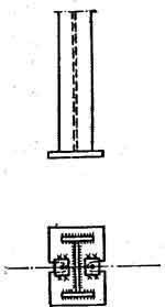
In steel columns, they distinguish: the upper part - headroom, on which the overlying structures are based; rod - the main part of the column, transferring the load from top to bottom; base (shoe) - the lower part of the column, which transfers the load from the rod to the foundation.
Steel columns by design are solid and through (Fig. 83).solid columns are used, as a rule, at high loads and low heights. The simplest solid column is obtained from one rolled double tee. Its disadvantage is the relatively small lateral rigidity. The most common are composite I-sections from rolled profiles or sheets welded together along the entire height. Through (lattice) columns used for high building heights. They consist of separate branches connected by braces or planks.
Steel columns can be of constant section (Fig. 83, a), stepped (Fig. 83.6) and separate type (Fig. 83,in ).
Rice. 83. Types of steel columns: a - constant section; b - step; in -separate
In columns of constant section the load from overhead cranes is transferred to the column rod by means of consoles on which the crane beams rest. Such columns are used for cranes with a lifting capacity of up to 20 tons.
Stepped columns the most common. The under-crane part of such columns consists of two branches connected by a grate, and the over-column consists of one branch. In the middle columns, both branches of the crane runway are designed from I-beams, in the extreme ones, the outer branch, for ease of pairing with the wall, consists of a channel or two corners connected by a sheet.
Separate type column consists of two branches (tent and crane), connected to each other, but separately perceiving the load from the tent (cover) and the crane.
Steel columns are attached to the foundation with a shoe (Fig. 84). The main part of each shoe is a planed steel plate (base plate) 40 ... 75 mm thick, on which the column rests with a milled end. In heavily loaded columns, traverses and ribs are installed to evenly transfer pressure to the base plate.
Rice. 84. Bases of steel columns a - articulated; b - hard
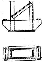
The shoe is attached to the foundation with anchor bolts. The upper plane of the foundation is positioned so that the shoes do not protrude above the floor level and do not interfere with movement around the workshop. The shoes and lower parts of the columns in contact with the ground are covered with concrete to prevent corrosion.
To support the outer walls between the foundations, foundation beams are laid, as with a reinforced concrete frame.
Yu. M. Solovey Fundamentals of the construction business. - M.: Stroyizdat, 1989. - 429s.
The frame elements of one-story buildings are vertical supports - columns and horizontal elements - crossbars in the form of beams or trusses, forming frames. Such load-bearing structures are called linear. In some cases, the crossbars of the frames of one-story buildings perform a broken and curvilinear outline. In addition, there are one-story buildings with vertical load-bearing structures, the spans between which are covered with spatial structures - shells.
The most common are single-story industrial buildings with a frame of prefabricated reinforced concrete or steel linear structures. A mixed frame is also used, in which individual elements are made of various materials. Such buildings are erected from standard unified structures, according to various constructive schemes, depending on the adopted column pitch.
If the pitch of the building columns in all rows is 6 m, then the beams and trusses covering the spans are also laid in increments of 6 m. If the pitch of the columns is 12 m, then the beams and trusses are laid differently. In one case, the trusses are also placed in increments of 12 m and pavement slabs 12 m long are laid on them. Another solution is that in the direction of the 12-meter pitch of the columns, beams or trusses, called rafters, are laid on them, and rafter beams and trusses covering the span, located in 6 m increments.
With this solution, truss beams and trusses through one rely either on columns, or on rafter beams or trusses. In this case, the 12-meter step of the columns is taken only for the inner rows of columns, and the columns of the outer rows are set in increments of 6 l, and along the outer rows all roof trusses and beams rest only on the columns.
The spatial rigidity and stability of such buildings, consisting of transverse frames, are provided by pinching the columns into the foundations of the building, fastening the frames together in the longitudinal direction with strapping and crane beams, covering disks, as well as setting stiffness ties along the rows of columns and between roof trusses.
Unified standard reinforced concrete columns of one-story industrial buildings are made of solid square or rectangular sections and through two-branch sections. For buildings without overhead cranes, without overhead and with overhead transport, with a building height from the floor to the bottom of the supporting structures of the coating of 10.8 I, smooth (cantileverless) square columns are used. Small consoles have only columns in the middle rows for better support of the supporting structures of the coatings on them. With a step of 12 m, spans up to 24 m and a height of up to 10.8 m, rectangular columns (500X600 mm) are used.
For buildings equipped with overhead cranes, depending on the height of the column, the step between them and the span, as well as the carrying capacity of overhead cranes, solid rectangular-section columns with cantilevers to support crane beams and through two-branch ones are used. In addition to these columns, the series of unified columns of one-story buildings includes solid and through columns for end and longitudinal half-timbered houses, as well as through columns for buildings without overhead cranes.
Rice. 1. Supporting the roof beams on the rafter beams: 1 - column, 2 - rafter beam, 3 - roof beam, 4 - roof slab
Rice. 2. Prefabricated reinforced concrete columns of one-story industrial buildings: a - solid outer rows for buildings without overhead cranes, b - the same, middle rows, a - solid outer rows for buildings with overhead cranes, d - the same, middle rows, d - through two-branch extreme rows, e - the same. middle rows
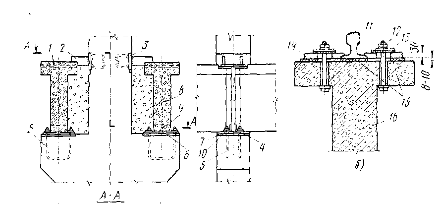
Rice. 3. Prefabricated reinforced concrete column of the extreme row with steel embedded parts: 1 - steel sheet with anchors for attaching the crossbar, 2 - embedded part for attaching the top of the crane beam, 3 - hole with a tube for slinging the column, 4 - steel sheet with anchors for attaching the crane beams, 5 - embedded parts. aphids for fastening wall fencing elements
Rice. 4. Prefabricated reinforced concrete roof beams of one-story buildings: a - single and gable span, b - single-slope span 12 m, c - with parallel belts with a span of 12 m, d - gable with a span of 18 m .. O - with parallel belts with a span of 18 m
The joints of the columns with the foundations are made of glass type, and to support the columns of the crossbars (beams and trusses) of the roof and crane beams, as well as to fix the elements of the wall fencing on the columns, flat steel parts and sheets with anchors are laid in them. On fig. 90 shows a solid column of the extreme row with a crane console, equipped with embedded parts.
The linear load-bearing structures of the roofs (crossbars) of one-story frame buildings are, as mentioned above, truss beams and trusses. In addition, arches are sometimes used for large spans. To load-bearing structures coverings of one-story frame buildings also include rafters and trusses.
Unified prefabricated reinforced concrete roof beams are used with a span of 6, 9, 12 and 18 m at a step of 6 m. Beams with a span of 6 and 9 m are made of single and gable tee sections. With a span of 12 m, beams are single-pitched, gable and with parallel chords, and with a span of 18 m they are gable and with parallel chords, as well as single-pitched with a broken lower chord.
The broadened supporting part of the beam is laid on steel sheets embedded in the column heads and fixed with anchor bolts protruding from the column supporting sheets and passing through the supporting sheet, which is welded to the beam support, followed by welding of the supporting sheets.

Rice. Fig. 5. Detail of the node supporting the roof beams on the column: 1 - steel sheet with anchors, '2 - support sheet of the beam
Unified prefabricated reinforced concrete roof trusses are used with spans of 18, 24 and 30 m at a step of 6 and 12 m. According to the outline, the trusses are segmented with a broken upper belt and with parallel belts. Segment trusses are used for pitched roofs, and with parallel belts - for flat roofs.

Rice. 6. Prefabricated reinforced concrete roof trusses: a - segmented with an upper broken belt, b - with parallel belts installed on columns, c - the same, installed on truss trusses at both ends, d - the same, installed at one end on the column, the other - to the truss farm

Rice. 7. Prefabricated reinforced concrete truss structures: a - a beam for buildings with a pitched and flat roof, b - a truss for buildings with a pitched roof, c ~ the same, for buildings with a flat roof

Rice. 7. Prefabricated reinforced concrete roofing arch with a span of 30 m

Rice. 8. Schemes of connections between reinforced concrete columns: a - cruciform (cross), o - portal
Trusses with a span of 18 and 24 m are delivered to construction sites in finished form, and with a span of ’30 m - in the form of two halves, which are enlarged into a whole farm before installation. The support of trusses on columns is performed in the same way as the support of beams.
The unified structures include prefabricated reinforced concrete rafters and trusses with a span of 12 m.
Rafter beams are intended for buildings with both pitched and flat roofs. The truss trusses shown in fig. 6, b, are intended for buildings with a pitched roof only, and the truss trusses shown in fig. 6, c, - for buildings with a flat roof. The fastening of the rafter beams and trusses to the columns is carried out by welding. To support the rafters and trusses on the rafters, the latter have base plates with anchor bolts.
For large spans (30 m or more), sometimes prefabricated reinforced concrete arches are used instead of trusses. On fig. 95 shows the overlapping of the span with a reinforced concrete arch of an I-section with a tightening of prestressed reinforced concrete.
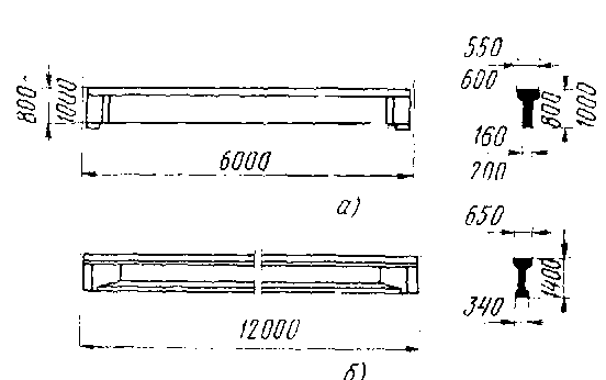
Rice. 9. Prefabricated reinforced concrete crane beams: a - T-section, 6 - I-section
Rice. 10. Design of fastening of crane beams and rails
When erecting buildings from prefabricated reinforced concrete structures, various connections are used. Their designs depend on the height and spans of buildings, the presence of overhead cranes in buildings, skylights in coatings and other structural characteristics of buildings.
Connections between columns in buildings with reinforced concrete prefabricated frames are placed at a height of more than 7-8 m. These connections are made of steel corners cruciform or portal. They are placed along the lines of the building columns in the middle of each temperature block. The connections are fixed with the columns by welding the scarves of the crosses of the connections with embedded parts in the columns. If there are overhead (support) cranes in one-story industrial buildings, the crane beams that carry the load from the cranes are at the same time connections along the columns in the longitudinal rows.
Unified prefabricated reinforced concrete crane beams are made of tee section with a vertical wall thickened on the support, as well as with a broadened lower chord in the form of an I-beam. Beams are produced for spans of 6 and 12 m under various loads from cranes with a lifting capacity of 10 to 30 tons. The height of the beams is 0.8; 1.0 and 1.4 m. Reinforced concrete prefabricated beams are also used for cranes with a higher carrying capacity - up to 200 tons. At the same time, the height of the beams for a span of 6 m is up to 1.2 m, and for a span of 12 m - up to 2.0 m. More often, steel beams are used for such cranes.
Crane beams are fixed on the consoles of the columns, on anchor bolts passed through the base sheet, which is welded on the supporting part of the beam, followed by welding. At the top, the beam flange is attached to the shaft of the crane part of the column with a flat steel vertical bar welded to the embedded parts of the beam and column, and the gap between the beam and column is filled with concrete mix.
The track rails of overhead cranes are laid on the surface of crane beams on an elastic gasket made of rubberized fabric with a thickness of 8-10 mm and fixed every 75 cm along the length of the beam with presser feet.
The presser feet are also placed on elastic gaskets and fastened to the beam with bolts with washers and cottered nuts through vertical holes with embedded bushings in the upper shelf of the beam.
Steel frames are mainly used for large spans and significant crane loads. In some cases, with large spans (30 m or more), the frames are made of mixed structures - reinforced concrete columns and steel trusses.

Rice. 11. Structures of steel columns: a - solid constant section, b - solid variable section. 6 '- through variable section, g - through with separate branches of constant section
The column rod is made differently depending on the load on the column and its height. On fig. 11 shows a solid column of constant cross section from a rolled or welded I-beam. There is a welded console to support the crane beam. On fig. 11.6 shows a solid column of variable section, (the crane part of which is made in the form of an I-beam, and the crane part is of a complex shape.
On fig. 11, c shows a through column of variable section, the crane part of which has an I-section, and the crane part consists of two branches - the outer, tent, channel section and the inner, crane, I-section.
The branches of the crane part of the column are interconnected by a lattice of corners, and sometimes by horizontal diaphragms made of sheet steel, and at the top under the crane beam - by a traverse. Columns of this design, designed for installation in the middle row, with crane beams supported on both sides, have both branches of the crane part of the I-section, interconnected by a lattice of angles and a traverse under the crane beams. The overhead part of the I-section column in this case rests on the middle of the traverse.
On fig. 11, d shows a through column, which has separate branches - a tent and a crane runway of constant section, interconnected by horizontal strips of sheet steel.
![]()
Rice. 12. Structures of the bases of steel columns: a - with fixing with anchor bolts of the supporting ones. slabs, o - with anchor traverses)! for bolting; 1 - overlay, 2 - bearing surface of foundations, 3 - holes for anchor bolts, 4 - anchor bolts. 5 - upper sheets of traverses, 6 - stiffening ribs (console) traverses
Column bases are performed differently depending on the size and design of the columns, as well as on the nature of the loads acting on the column. The most common are bases with base plates welded to the lower end of the column, directly fixed to the foundation with anchor bolts and with cantilever anchor traverses welded to the shelves of the column branches. In the first case, the upper surface of the foundation is located 40 cm below the floor level, in the second - 100 cm. After installing, aligning and fixing the columns on the foundations, their bases are concreted to protect them from corrosion.
Steel truss trusses of building coverings are used in different shapes depending on the span they cover, used roofing material, the adopted space-planning decision and other conditions.
Polygonal and triangular trusses are widely used. Farms are also used with parallel upper and lower belts. Belts and lattice (braces and racks) of trusses are made welded from paired rolled steel corners of various sections. At the nodes, the elements of the lattice with belts and are connected to each other on gussets (kerchiefs) made of sheet steel. Pairs of corners that make up belts and gratings are connected at certain distances along the length by welding with flat steel gaskets.
More often, unified polygonal steel trusses are used with a span of 24, 30 and 36 m with the same height lx on supports of 2.2 m and in increments of 6 and 12 m. The distances between the nodes of the upper belt of trusses are 3 m, and when used in coatings reinforced concrete slabs 1.5 m wide trusses are made with additional lattice elements - trusses, shown in fig. 101, but dotted. The slope of the upper belt of such farms is 1: 8.
On steel and reinforced concrete columns, the trusses are installed with the support unit of the lower belt and fixed on bolts. When leaning on the outer row of columns, a support post of an I-section is bolted to the truss, which is simultaneously connected by bolts to the head of the column.

Rice. 13. Steel roof trusses: a - polygonal, b - triangular, c - polygonal unified
On the supports along the middle rows of columns, the trusses converging on them are also fixed support nodes the lower chord is bolted to the column, connected to each other by bolts along the upper and lower chords, and above the support between these chords, a cross-section support post of two corners is bolted. Such fastening of trusses on columns is not rigid.
Farms are delivered to the construction site in halves (shipping marks) and before installation they are enlarged to whole. The halves are connected first with bolts, and then by welding A joints.
In cases where the step between the trusses is 6 m, and the step between the columns of the inner rows is 12 m, truss steel trusses are used and truss trusses are supported on them in the middle of the 12-meter step.
Under-rafter trusses are performed similarly to truss trusses, but with parallel belts and a height of 2.68 m. On columns, truss trusses are attached with a lower belt to the side of a steel over-column 0.7 m high, and fastened with upper belts to each other. In this case, the truss trusses spiral through one supporting part onto the patellas fixed on the columns, and onto the tables available on the truss trusses.
Triangular truss trusses with a slope of the upper belt 1: 3.5 are intended for overlapping single-span roofless, unheated premises with a roof made of asbestos-cement sheets. Such trusses are made with a span of 18, 24, 30 and 36 m with the transfer of loads to them through the nodes of the trusses after 1.5 m from the steel girders of the coating, to which roofing asbestos-cement sheets are attached.
Bonds to give spatial rigidity and stability steel frames single-story buildings are also installed along the longitudinal rows of columns, as in buildings with frames made of prefabricated reinforced concrete structures, as well as along the planes of the upper and lower chords of trusses and in the longitudinal planes between trusses.
Unified steel crane beams have two types of cross-sectional profiles. In buildings with a column spacing of 6 m and overhead cranes with a lifting capacity of up to 75 tons, I-beams of an asymmetric profile are used with an upper chord developed in width, which perceives not only vertical loads from cranes, but also horizontal braking forces.
For large spans and lifting capacities of cranes, beams of a symmetrical profile are installed with the same width of the shelves of the upper and lower chords. With such beams, horizontal braking forces from cranes are perceived by braking beams or trusses located horizontally in the plane of the upper chord.
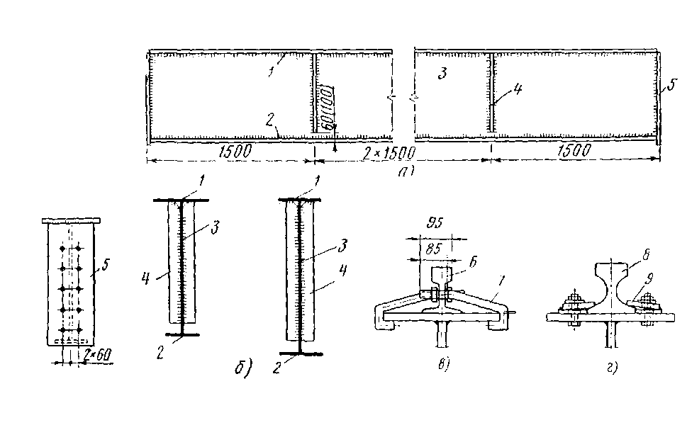
Rice. 14. Steel crane beams and details of attaching rails to them: a-general view of the beam, b-cross-sections of beams of asymmetric and symmetrical profiles, c - fastening of a railway rail, d - the same, a special profile rail; 1 - upper chord of the beam, 2 - the same, lower, 3 - beam wall (vertical), 4 - transverse stiffeners, 5 - support rib, 6 - railway rail, 7 - fastening hooks, 8 - special profile rail, 9 - fastening paw
On the console of the columns, the crane beams are supported by the planed lower edges of the supporting ribs and fixed with anchor bolts passed through the support plate and the bottom chord of the beam. The top of the beams on the supports is fixed with the help of overlays or designs of brake beams or trusses. Between themselves on the supports, the beams are bolted through the holes available on the sheets of the supporting ribs.
With spans of more than 12 m, crane beams are made lattice in the form of trusses.
The railway rails of the crane tracks are attached to the upper chords of the crane beams using hooks with a diameter of 22 mm, and the rails of a special profile are fastened with paws, bolted to the upper chord after 75 cm.
Sometimes linear structures made of wood are used as load-bearing elements of the coatings in the coatings of one-story frame buildings. Such structures are wooden beams and farms, as well as wooden structures in combination with their individual elements made of steel.
With small spans, wooden roof structures are made of glued beams, as well as glued I-beams with plywood walls. Glued wooden structures are very progressive. Of these, the upper belts of metal-wooden trusses and wooden glued arches with metal puffs are also made. There are also other designs of wooden load-bearing elements of the coverings of frame buildings. Sometimes also used wooden racks in frame buildings. Wooden structures are protected from fire with flame retardants.
