Overlapping between floors in a wooden house. Beam ceilings: device, types
In the process of building private houses made of wood, brick or concrete blocks, they use wooden floors. Wooden floors in the house have a number of advantages, and most importantly, they do not overload the walls. They do not require the use of heavy equipment to fix them. This material has high strength and long service life. Installing ceilings is not a difficult process and it is quite possible to do it yourself.
Floor device
Overlappings are beams that are fixed in the walls of the house and serve as a solid foundation for the rest of the building elements. In order for the structure to be able to withstand the entire load of the structure, it is necessary to carry out the correct calculation. As a rule, glued beams, logs or planks are used for beams. Softwood timber is ideal for floors, because. they have high bending strength, but hardwoods are vulnerable, and under heavy load can be deformed. Boards or plywood are fixed on top of the structure, and sheathed with a front covering. It is also possible to install lags on the floor, which are attached to the beams. It is worth considering that the ceiling from the first floor will serve as the ceiling, and from the second floor it will serve as the floor. To do this, it is necessary to sheathe the upper part with a floor covering, and the lower part with clapboard or drywall.
Between the beams, as a rule, a space is formed, which is insulated and waterproofed, which provides additional protection from moisture.
Important! If the attic is not planned to be heated, it must be insulated. If the second floor is planned to be used as a living room, the flooring does not need to be insulated, but to reduce noise, it is necessary to lay soundproofing material.
Types of floors and basic requirements for them
- Interfloor. The main function is to separate floors;
- Basement. The main function is to separate the basement from the house;
- Socle. The main function is to separate the floor from the cold basement structure;
- Attic. The main function is to separate the floor of the house from the attic.
Bearing capacity can be noted:
- beam, consist of a bearing part and filling;
- beamless, consist of homogeneous elements.
And now we will analyze each type in more detail.
Beam construction. In its supporting base there are beams located at the same distance from each other, fillings are laid out on top of them, due to which the whole structure performs the function of a fence. The beam structure most often serves as a floor in wooden house. It is characterized by a span width, so they are used for:
- interfloor connection with a width of 5 m;
- attic space 6 m wide.
Important! Metal beams can be used for any span width.
As a material, a tree of coniferous and deciduous species is used. On the upper part they make a flooring, which also serves as a floor. The design consists of beams, rolling, insulation and floor. The advantage of this structure is quick installation, without the use of special tools and equipment. The wood flooring itself comes out light and not expensive. Among the shortcomings can be noted, high flammability.
Beamless design. It is made of multi-hollow or solid slabs. The width of the span is calculated based on the features of the house. The advantage of this type is:
- high strength and ability to withstand heavy loads of the building;
- unlike wood, they do not rot.
The disadvantages include:
- with their device, heavy equipment cannot be dispensed with;
- products are produced in certain sizes, with a non-standard project at home, it may be difficult to install them.
Material calculation

Before the construction of floors, it is necessary to perform the correct calculation of materials. The length of the beams directly depends on the width of the span and the method of their fastening. When fixing into the grooves of the wall, the length of the beam is calculated by adding the span to the depth of insertion of the ends of the product into the grooves. The width is maintained at a distance of 1 m. The calculation of the beams is carried out as follows, the placement of the extreme products at a distance of 50 cm, and the remaining beams are installed evenly in the span space.
It should be noted that beams can be different shapes. For example, square, round, rectangular. In construction, a rectangular product is most often used, the width of which is 50-160 mm, and the height is 140-240 mm. The cross section of the product directly depends on the expected load of the house, the width of the spans and the placement of the beams. The load is calculated as follows: the load of the dead weight of the product is summed up with the temporary load (200 kg). In practice, the load value is used in the value of 320-400 kg, and for the attic - 200 kg.
Important! If it is planned to install a heavy and powerful bath or pool in the house project, the calculation must be carried out individually based on the project plan.
It should be noted that with large spans, sagging of the beam is possible. To solve this problem, columns or supports are erected, thus protecting the structure from deformation and destruction. If you are not sure about the correct calculation, you can use ready-made tables with the given values. Each value is given with respect to perceived future load.
Beam installation
Installation of wooden floors is carried out taking into account a certain technology. The whole process is divided into several important steps.
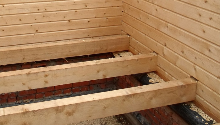
Installation of beams. Before making the installation of floors, it is necessary to treat with an antiseptic. If the ends of the beam rest against concrete, it is necessary to wrap their edges in two layers of roofing material. Next, a small place is prepared in the form of a nest and a beam is inserted into it, leaving a small gap of 2-3 cm. The free space is filled with mounting foam or insulation.
Installation of roll. To the side faces of the beams, small bars of 4 cm are fixed, then the reel is fixed on these bars. The roll itself is made of boards, in the form of a shield. The plates of the structure must be pressed tightly against each other and fixed with self-tapping screws to the beam.
Laying of heat-insulating material. An important component in wooden structures is the laying of heat-insulating material. Insulation performs two main functions, firstly, it isolates sound well, and secondly, it also insulates the room. For laying insulation, you must select the material. You can use mineral wool, polystyrene foam, expanded clay, sand or shavings. Experts recommend using mineral wool. This material is able to breathe, easy to work with and has high performance in home insulation. As soon as the roll is firmly fixed, a layer of thermal insulation is laid on top of it, the thickness of which is 10 cm, and for the attic room - 25 cm.
Expert advice! After the structure of the floor beams is ready, bring the ceiling to normal. You should not seal it and knock out rough boards, the gaps will create ventilated channels for the wood.
The main mistakes in the installation of floors
If you decide to do the installation of floors yourself, approach this matter professionally. With insufficient knowledge of the process, many mistakes can be made that will lead to the construction of an unsafe structure for all residents. Let's take a closer look at common mistakes:
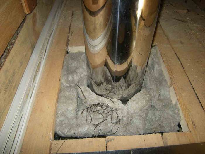
- Installation of beams near the chimney at a distance of 40 cm. As you know, the tree burns, and the overlap made in this way can be charred under the influence of high temperature. In addition, the surface of the chimney must be plastered with a special mixture of 2 cm.
- The wood for the lag must be dry. If you bought wood with signs of moisture, you should let the material dry, this will take about six months. It is highly undesirable to erect any structure from raw wood and is fraught with the fact that the house may simply collapse.
- After installing the floors, be sure to treat them with a special agent against rotting, fungus, mold and bark beetle. With untreated wood, there is a high probability of attack by external irritants. Eliminating such a problem is difficult and expensive, because. for this, the floors are removed and all the work to eliminate the problem is performed by professionals.
Overlaps by wooden beams connect the floor of the building with the attic, basement or upper floor. The design serves to evenly distribute the loads on the walls of the building and is the basis for the rough flooring of the upper room and the ceiling lining of the lower one.
Overlapping on wooden beams is necessary to evenly distribute the loads on the building.
The arrangement of ceilings using timber beams makes it possible to do without lifting equipment and to carry out installation by a team of 3-4 people. The speed of installation of load-bearing structures of this type is higher than when using other materials. Ceilings on wooden beams are more often mounted in one-story houses private sector, frame buildings.
Types and characteristics of floors on wooden beams
Floors with load-bearing elements made of wood may vary:
- design features;
- material of load-bearing, enclosing elements and thermal insulation;
- connection method.
Floor beams are made of timber or logs hewn on one or 3 sides.
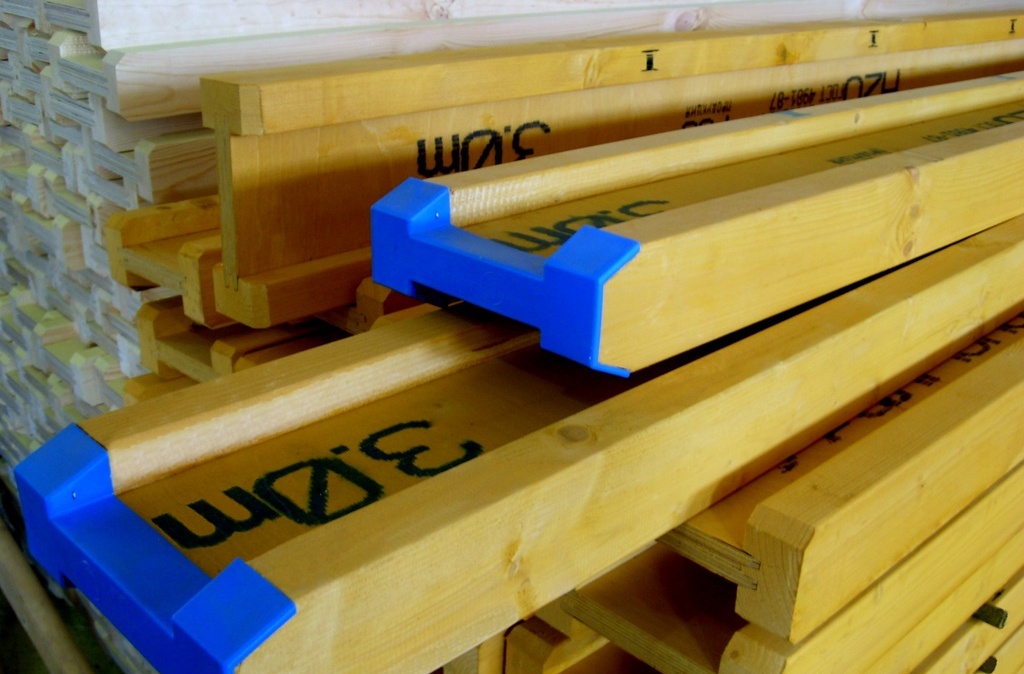
Floor beams are made from a bar of calculated section, edged boards, logs hewn on one or 3 sides. AT recent times widespread use of glued laminated timber, having standard sizes and correct geometric shape. This option for the manufacture of load-bearing elements is considered the most reliable.
Glued load-bearing elements are made to order and do not have to be cut to size. I-beam structures with a combination of wood and OSB are also used. For flooring equipment, beams made of hardwood and coniferous wood are used. They are pre-dried for at least 3 months. To increase the strength, additional layers of plywood, OSB or chipboard with a thickness of 12 mm or more are nailed to them. In places where beams are laid on internal walls, the connection is reinforced with clamps, brackets or boards with a thickness of 40 mm or more.
The overlap between the floor and the attic can be either an independent structure or an element of the roof frame. In the latter version, truss elements rest on the beams. The combination of the roofing system and the ceiling reduces installation costs, but the repair of the structure is more difficult. In addition, it has the worst soundproofing properties. When installing the basement, its reliable waterproofing must be carried out.
Principles for calculating floor elements
The interval between the beams, their length and section dimensions are selected in accordance with the parameters of the area to be covered. The maximum load during operation, the type of insulation boards, the weight of the ceiling finish are taken into account. The dimensions of the beams can be increased due to the peculiarities of the design of the premises. For interfloor structures, the load from equipment, furniture and people is taken into account.
Bearing elements must withstand a load of 200 kg / m 2, taking into account their own weight. Based on the structure of the building, the cross section and the spacing of the beams are calculated. The permissible deflection from the specified load is for basement floors - 1/250 of the beam length, for attic - 1/200. Restriction on the length of load-bearing parts for floors equal to 5 m, for attic - 6 m. The optimal ratio of height to width of the section of a rectangular element is 7:5, to the length of the beam - 1:24.
Beams made of logs are able to withstand greater loads than timber, but with increased deflection. The fastening of paired beams with bolts increases the resistance to loads by 2 times compared to unfastened elements. To determine the exact parameters of the supporting structure, you can use online calculators or special tables.
Laying and fastening beams
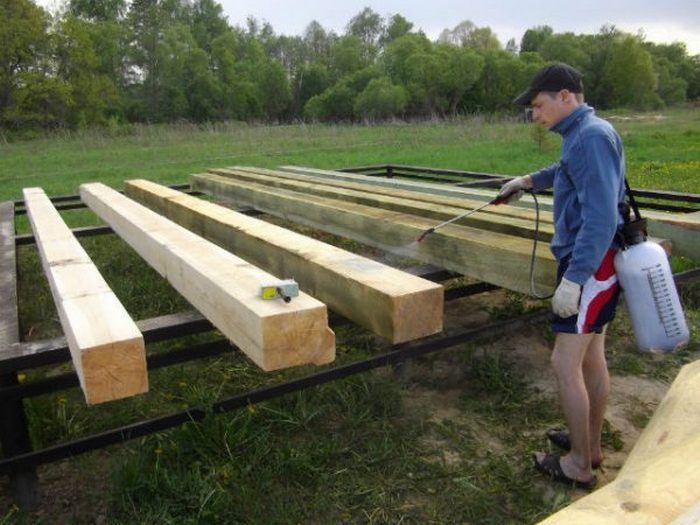
After taking measurements, the workpieces are sawn at an angle of 60 °. The side view of the beam should have trapezoidal contours. This shape of the ends contributes to better evaporation of moisture from the wood structure. The day before installation, the beams are impregnated with antiseptic and flame retardant compounds. The ends of the elements are not processed. The side surfaces of the edges of the beam, exposed to the seat, are smeared with resin and wrapped with roofing material.

For installation of the floor structure, tools and additional materials will be required.
- jigsaw and wood saw;
- ax, hammer;
- hydraulic level;
- tape measure, fishing line;
- keys, screwdriver;
- nails, screws, anchor bolts;
- staples, corners;
- roofing material, heat-insulating material;
- strong rope;
- construction goats, stairs.
First, the extreme beams are installed with leveling. Under their ends for alignment, wooden linings are placed, pre-coated with waterproofing mastic. Every third mounted beam is fixed with anchors.
The beam is inserted into the opening by at least 20 cm. The end should recede 5-8 cm from the wall. The extreme beams from parallel walls should be set at approximately the same distance. A rail is attached to this space, separated from the bearing part by a roofing material. Fishing lines are stretched from the extreme elements, the rest of the beams are exposed along them. After adjusting the position of the beams, the landing nests are filled with mortar.
When laying on log walls, the beam is placed in the groove of the upper crown with preliminary laying of waterproofing material. If the installation requires hemming of the ends of the beam, it can be done no more than ¼ of the height of the element.
Formation of interbeam space
In addition to the load-bearing elements, the floor structure includes a run-up, an insulating layer, the floor of the upper room and the ceiling finish of the lower one. To lay the roll, cranial bars (5x5 cm) are attached to the beams, on which boards or panels are laid. You can use a slab.
For some types of ceiling finishes, a flat surface is required. In these cases, a quarter (fold) is sampled along the ends of the roll boards lying on the cranial bars. The run-up is covered with roofing material, putty can be made with a clay-sand mortar up to the middle of the height of the opening.
The openings are filled with various noise, hydro and heat insulating materials. Often used as a heat insulator mineral wool, sometimes - foam, polystyrene, etc. Backfilling can be made bulk materials(slag, sawdust, etc.) to ¾ of the height of the opening.
The thickness of the heat-insulating layer can be from 5 to 25 cm and depends on the purpose of the floor (attic, basement) and climatic conditions. Many experts do not recommend insulating with slag or expanded clay. With modern thermal insulation standards, the bulk coating will have too much weight.
To prevent moisture from penetrating into the insulation, a waterproofing film is attached before filing the ceiling of the basement and during the arrangement of the attic floor.
The insulating material in the structure of the intermediate floor mainly performs noise-absorbing functions. In order to reduce the penetration of sounds into the lower floor when moving around the upper floor, its ceiling is attached to additional beams that are not directly connected to the main carriers.
Upstairs floor installation

After rolling and laying thermal insulation material a reinforcing mesh is applied and a screed is made with cement mortar. The concrete surface will act as a subfloor. For the attic floor, you can install transverse logs on the beams and sheathe the floor with a grooved board.
Floors can be installed directly on wooden beams or on logs previously fixed to them. The first method of flooring is distinguished by the best structural strength, since the beams are rigidly supported by load-bearing walls.
It is easier to perform the work on laying the coating along the logs, and such a floor structure increases noise absorption at times, and contributes to better ventilation of the wood. Noise isolation increases with the installation of a "floating" floor. The design is not fixed rigidly in the walls, which also increases protection against the spread of sounds.
The flooring can be made of chipboard or planed floorboards, as finishing parquet, laminate or linoleum is used. The ceiling under the ceiling is finished with sheets of dry plaster or plastered along the edge.
The cost of arranging floors can be 15-20% of the cost of installing all the main structures of the building. The cost of producing the work is about a quarter of the cost of the required materials. Therefore, the use of wooden beams as load-bearing elements and self-arrangement of the floor will help to significantly reduce construction costs.
Any building has a system of horizontal ties that distributes the load between the walls of the house. Of course, in a wooden structure, the floors must be wooden. The advantages of such structures include low weight, providing high level thermal insulation and sound insulation, the ability to build a building even in frosty winter.
Depending on the premises in a house made of timber or logs, operating conditions may differ. This must be taken into account when constructing floors. There are interfloor and attic floors. Structures between floors separate adjacent floors, where the air temperature is almost the same. Therefore, they do not need warming. Such structures need only soundproofing. However, there is an exception to the rule - at the basement floor, the floor must be insulated and also protected from moisture.
Special attention should be given to attic floors in a wooden house, as these structures separate the cold attic from rooms with a higher temperature. In addition, they require excellent sound and thermal insulation. Floors located in bathrooms, bathrooms and showers need additional protection. Since they separate rooms with high humidity, they must be waterproofed.
Floor construction
All floors consist of two main elements: enclosing filling and load-bearing structure. If the coating is wooden, then the main load-bearing structure there will be a beam. Beams are able to withstand not only their own weight, but also filling, as well as loads during operation. The load is transferred to the poles and girders.
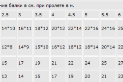
It is very important to choose the right beams for the ceiling, as incorrect calculations can cause deflections and even structural failures. When choosing a section, it is necessary to make a calculation in such a way that the beam height is not less than 1/16 of the span width, and the beam width is about 1/2 of this value. The following table will help you choose the dimensions of the beams:
| Cross-section of beams depending on the length of the span, m | |||||||
| 3.0 | 3.5 | 4.0 | 4.5 | 5.0 | 5.5 | 6.0 | |
| 150 | 5x14 | 5x16 | 6x18 | 8x18 | 8x20 | 10x20 | 10x22 |
| 200 | 5x16 | 5x18 | 7x18 | 7x20 | 10x20 | 12x22 | 14x22 |
| 250 | 6x16 | 6x18 | 7x20 | 10x20 | 12x20 | 14x22 | 16x22 |
| 350 | 7x16 | 7x18 | 8x20 | 10x22 | 12x22 | 16x22 | 20x22 |
The load on wooden floors is calculated by summing their own weight and the level of temporary loads that occur during the operation of a timber or log building. The mass of floors between floors in a wooden house and attic floors is related to the design features, as well as the type of insulation that is used. The level of temporary loads on the interfloor ceiling is calculated as 200 kg / m2, and on the attic - 100 kg / m2. The temporary and own loads must be added to calculate the level of the total load per 1 m2 of overlap.
The distance between the beams is 50-100 centimeters. You need to understand that the openings between the wooden beams also have a certain load, so you should not make them more than 100 cm. To use wood economically, choose beams from 15 to 18 cm high and 5 cm thick. 60 cm, and the calculation takes into account that mineral wool insulation will be used. Wooden structures need additional protection against mold and decay, so for their manufacture, you can use a tree that has been cleaned of bast and bark, and the humidity level should not exceed 20%. Of course, nothing should affect the strength of the beams: no knots, no slanting, no graininess. Structural elements must be impregnated with antiseptics and fire retardants.
The device of wooden floors
When installing wooden beams, they must be laid parallel and along a short span section. The distance between the structural elements must be the same. Cutting beams into crowns wooden frame it is carried out with a frying pan, after which the mechanical processing of the ends and their impregnation with the help of antiseptics is performed. At the same time, the wooden beam should not rest less than 10 cm on the purlin or wall. For internal walls that separate rooms with the same temperature, and for external walls that are more than half a meter thick, closed or open beam terminations can be used.
Wrap the ends of wooden structures that rest on the outer walls with roofing material (roofing paper), burn or treat with an antiseptic agent, if on the inside, then under the ends put a roofing material or roofing felt in 2 layers. The ends must not be closed or treated with bitumen. To reduce sound vibrations that are transmitted to the walls from the ceilings, it is recommended to use soundproofing pads. For these purposes, you can use rubber or felt impregnated with antiseptics. If you need to make an opening in the ceiling, then the builders install an additional crossbar, which serves as a support for a beam or several beams.
Another important structural element wooden house- rolling. It takes on the load from the insulation layer and transfers it to the beam. The roll is made from boards, which can be made of transverse boards, longitudinal boards or a combination of transverse longitudinal boards. The shields are supported by cranial bars (holes) attached with nails to the side parts of the beams. The cross section of the cranial bars should be 4x4 or 5x5 centimeters. Shields can be made of plywood, slab, gypsum slag, fiberboard, or other sheet building materials that can support the weight of the backfill. Separate rolling elements must be adjusted to each other very tightly. When constructing decking and rolling, it must be understood that a large number of wooden elements in the floor leads to an increase in the level of vibration under mechanical loads, which is another source of noise. To reduce the noise level, the individual elements must be combined into a sheet pile. The finished roll can be covered with roofing felt or roofing felt, as well as a layer of insulation. The attic coating is filled to a thickness that corresponds to the temperature outside.
You can select the appropriate material in accordance with the table below:
| Type of insulation | Volume weight, kg/m3 | Backfill layer thickness (mm) at ambient temperature, °C | ||
| -15 | -20 | -25 | ||
| sawdust | 250 | 50 | 50 | 60 |
| wood shavings | 300 | 60 | 70 | 80 |
| Agloporite | 800 | 100 | 120 | 140 |
| Boiler slag | 1000 | 130 | 160 | 190 |
If a wooden house is being built on two floors, then plank flooring should be laid on wooden beams, and the ceiling should be hemmed. At the same time, floor logs are laid on beams. The thickness of the wooden boards should be at least 1/20 of the distance between the beams. For bathrooms and toilets, the ceiling must be such that moisture does not penetrate through it. Typically, a waterproofing layer is laid on a solid wooden deck. The boards are joined into a tongue and groove, and any high-quality sealant is placed in the grooves between the boards. Particular attention is paid to areas where the ceiling is connected to the wall.
The elements are interconnected in a certain way, and the design works as a whole.
Beam ceilings classified according to the material of the beams. In modern low-rise housing construction, wooden, steel and special beams for cellular floor blocks are used - for a precast-monolithic version.
Option for the location of floor beams: a - type of floor; b - transfer of loads from floor beams to the wall; 7 - floor beams; 2- bearing wall; 3 - non-bearing wall; 4 - plank floor or base for a clean floor (black floor boards); 5 - transfer of loads to the load-bearing wall
Interfloor ceiling on wooden beams
In our country, where there is a lot of natural material - forests, wood is a traditional building material. In stone houses, floors are often made on wooden beams. Of course, wood is an environmentally friendly material, especially not treated to increase fire and bioresistance.
Contrary to popular belief about the fragility of wood, wooden floors with proper construction and proper operation last a long time.
It is interesting. An example is the houses of St. Petersburg, which were built when he was the Russian capital. Wooden floors have not only low-rise estates, but also six-, seven-story houses in the center of St. Petersburg, former tenement houses. For 200 years, in a damp climate, the houses have been standing without reconstruction and are a residential historical fund.
You can also use Moscow as an example. True, here the number of storeys of houses is mostly smaller, but the houses are also much older than the houses in St. Petersburg. So, in the old central districts of Moscow (for example, in the area of Rozhdestvenka St. and Kuznetsky Most, on the Boulevard Ring and other streets), houses are 300 or more years old, and not all of them have been reconstructed.
Of course, in those distant times, it was not timber that was laid, but logs, which, in comparison with timber, are a stronger and more durable building material.
Wooden beams are easy to manufacture and do not require complex mechanical equipment.
Material and parameters of wooden beams
As wooden beams, as a rule, timber is used. A beam is a log sawn from four sides. Made from coniferous wood. On small spans up to 2 m, boards 25, 32 or 40 mm thick can be laid, placed on edge and knocked together with nails - 2 or 3 boards each. Of course, logs can also be used as the most durable material: but in modern life this is justified only with a special design of the room, or with an appropriate finish of the ceiling and floor construction for such a ceiling.
The parameters of the beam sections depend on the size of the spans to be covered and the steps with which the beams are laid, as well as on the magnitude of the permanent and temporary loads perceived by the ceiling. Roughly, you can use the data in the table.
| Name of material*, parameters bxh**, mm | Span P, mm | Pitch W (no more), mm*** | Name of material*, parameters bхh**, mm | Span P, mm | Pitch W (no more), mm*** |
|---|---|---|---|---|---|
| Beam 50x150 | Beam 100x200 | ||||
| Beam 100x150 | Beam 150x200 | ||||
| Beam 150x150 | Beam 175x200 | ||||
| Beam 150x175 | Beam 200x200 | ||||
| Beam175x175 | Beam 200x250 |
* Data of the current range of lumber in accordance with GOST 24454-80*; timber length from 1 to 6.5 m with a gradation of 250 mm.
** In the section parameters, the smaller parameter b is the section width, the larger h is its height.
*** The calculation of the step includes a payload on the ceiling of 200 kgf/m 2 , the mass of wooden beams and a soundproofing layer of mineral wool boards with a density of 100 kg/m 3 . In the case of backfilling with expanded clay, the step is reduced by 20% (this approximation can only be taken for educational purposes, in practice a competent calculation is needed).
A feature of wooden beams is the fact that on large spans they guarantee the strength of the floor, but do not ensure the rigidity of the floor: the floor becomes "unsteady". In principle, the "unsteadiness" of the floor is checked by calculation, which is not always possible to do. Therefore, in order to eliminate the possible "fluctuation" of the floor, the beams are laid with a small step - 500 ... 600 mm, even if the strength calculation of the beams shows the possibility of a larger step. Otherwise, you need to apply lags (see below).
Laying out floor beams and embedding them into the wall
The length of the beams is selected depending on the size of the overlapped span. Beams, as a rule, are laid along the smallest span if the overlapped room is rectangular. If the room is square, then the direction of laying the beams does not matter. The fact is that all the walls of a stone house can be classified as load-bearing, as they are strong enough to withstand the load from wooden beams.
The figure shows an example of the layout of wooden floor beams. The parameters of the beams are selected depending on the spans and steps. The section between the coordination axes A/2 and B is interesting. To form the floor, two auxiliary beams with a section of 150x150 mm are introduced here, on which beams with a section of 100 x 150 mm are supported. To reach one floor level, the auxiliary beams are embedded in the load-bearing walls below the rest to the height of their section, i.e. by 150 mm.
Also, perhaps, it is necessary to explain why a small span between axes 3 and 4 is covered with beams 150x150 mm? In fact, these beams cover a six-meter span between axes 1 and 4, and the load-bearing wall along axis 3 serves as an additional support for the beams. But, of course, you can also prepare separately beams for spans 1-3-4.
The attentive reader, of course, noticed that the step of the beams is not always subject to the modulus. Why this subordination is not necessary, we will see when we study the composition of the layers of interbeam filling. In addition, here the steps are shown without regard to the specific material of the walls in which the niches for the beams will be arranged, and this may somewhat, slightly, affect the size of the steps.
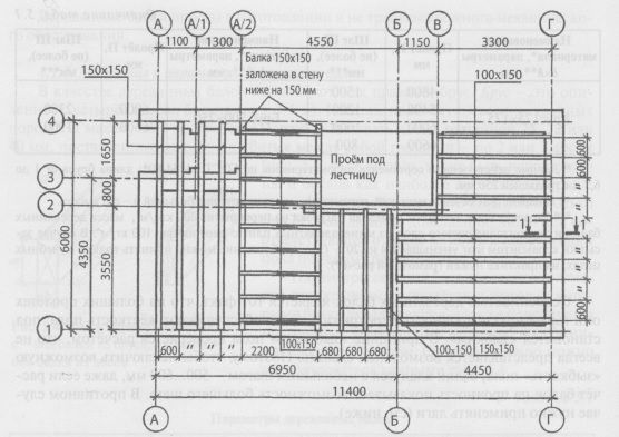
An example of the layout of floor beams
The beams are laid in niches specially prepared during the laying process in the wall. To ensure reliable and durable support, the depth of embedding the beam in a brick or any other stone wall must be at least 150 mm. The depth of the niche is determined in such a way as to ensure the depth of the beam embedded in the wall and leave a certain air gap (20 ... 30 mm), which excludes the contact of the tree with the stone back wall of the niche. In addition, an air gap will help prevent wood decay if air is allowed into the niche.
The niche is not filled with anything if the wall structure contains an insulating layer on the outside. In the event that no insulation is included in the wall structure (for example, the wall is built of ceramic stone, and the thermal protection of such a wall is provided), the niche can be a conductor of cold, since the remaining wall thickness is not enough here. Then in a niche we can get freezing and moisture condensation. To prevent this, the niche is filled with heat-insulating material. Expanded polystyrene is preferred as such a material, since, having closed pores, it is not saturated with moisture, which warm air from the room can carry with it. Of course, expanded polystyrene refers to combustible materials, but we are talking about wooden floors, in which, anyway, you need to be especially careful in terms of fire safety.
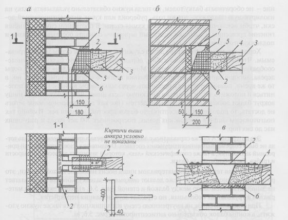
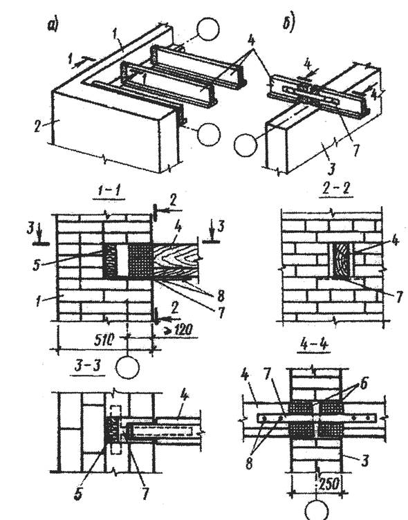
Embedding wooden beams into a wall: a - blind embedding of beams into an insulated wall; b - the same, into a wall without insulation and with the possible occurrence of cold bridges in a niche under the beam; c - open embedment of beams into the inner wall; g - type of anchor; 1 - mounting foam (preferably) or mortar; 2- anchor; 3 - wooden beam; 4 - beam antiseptic zone; 5 - the end of the beam wrapped with roofing felt; 6 - antiseptic board 32 mm thick (preferred) or several layers of roofing; 7- effective insulation.
Do not wrap the insulation with a film or place, say, in a plastic bag. This can lead to condensation in the closed space of the bag and, subsequently, to poor performance of the insulation; as a result - freezing of the wall.
The ends of the beams before laying on the wall are sawn off at an angle of about 60 ° ... 70 ° and treated with an antiseptic material. It will be reliable to wrap the ends of the beams with roofing felt or roofing material (roofing felt is preferable), but the ends of the beams are not covered to provide air access to the tree through its end part. A less reliable solution is not to wrap the beam with roofing paper, but then it is necessary to lay the beam on an insulating substrate: the same roofing felt, roofing material or a piece of antiseptic board to prevent contact between wood and wall stone. Otherwise, the wood will rot. An even more reliable option is to combine the wrapping of the beam and the substrate, as shown in the figure.
It is well known that wood lasts a long time if it remains dry and ventilated. To keep the tree dry, it is advisable to seal the gaps formed around the beam with mounting foam. Mounting foam, "closing up" the upper pores of the tree, protects it well from moisture from the room, but at the same time allows air to penetrate through the micropores into the niche. If you are not too lazy and put the boards not only in the lower part of the niche, but also overlay the entire niche around the beam with boards soaked in tar (as in modern world you can’t get tar, then an antiseptic will do), then the beams will stand for more than one century. This is how niches are prepared in Moscow houses built 300 years ago and still pleasing us.
It is interesting. And how did they cope with the decay of the tree in ancient times? After all, then there were no modern antiseptic compounds. It turns out that soot is an excellent natural antiseptic, as well as a specific “lacquer” that protects wood from moisture and fungus. She processed the beams.
A niche sealed with one or another material is called a blind seal, this is a common solution. Less commonly, they make an open seal, which involves not filling the gap between the beam and the wall with anything. Here, the savings in materials and labor costs are small, but the sound insulation of the floor suffers.
When supporting the beams on the inner wall, the insulation under them must also be laid, and the ends of the beams must be antiseptic.
To connect the walls with the ceiling, as well as to ensure the rigidity of the building, the beams in the niche must be fixed. The point is that the walls two-storey houses reach a height of seven or more meters, connecting only in the corners. If rigidity is not provided, the wall can go out of its plane with all the ensuing consequences. Anchoring beams into the wall will help to make the spatial "wall-floor" system rigid - creating horizontal discs floors. This can be done using T-anchors cut from flat steel. One end of the anchor is nailed to the beam, the other end is driven into the masonry. The anchor is nailed to the top or bottom of the beam. Anchors are attached to each or through one beam.
The ends of the beams resting on the internal walls are interconnected by steel strips nailed on both sides of the beams.
It is interesting. Puffs have always been used for beam ceilings, even in large buildings. For example, today on the building of the Trekhgornaya Manufactory factory, built at the end of the 18th century, you can see how the puff anchors go out onto the facade.
The figure shows the developed solution for the support unit of wooden beams on walls erected from aerated concrete or gas silicate blocks. As in the case of ceramic stone, the heat-shielding properties of aerated concrete make it possible not to insulate the wall. Therefore, a heater is laid in a niche.

Supporting wooden floor beams outer wall from aerated concrete blocks: 1 - aerated concrete main blocks; 2 - additional blocks; 3 - mineral wool insulation; 4- U-shaped blocks; 5- wrapped with roofing felt (preferably) or roofing felt end of the beam; 6 - wooden floor beam; 7- steel plate - connector (anchoring); 8 - dowel-screw; 9 - monolithic reinforced concrete belt.
Since the strength of aerated concrete blocks is lower than that of bricks, a monolithic reinforced concrete belt is prepared under the beam - it will take the load from the ceiling. Insulation and reinforced concrete belt are laid in a cavity formed by special U-shaped blocks. The end of the beam entering the niche is antiseptic and wrapped with roofing material, roofing felt, etc.
Beams are anchored using a sheet strip bent at a right angle - a connector, which is fixed to the beam and reinforced concrete belt with dowel screws.
This solution can be supplemented with those actions and elements that we spoke about in such detail when considering the figure.
Inter-beam filling in the design of the ceiling without the use of logs and with logs
Inter-beam filling is inherently enclosing and contains layers and elements, each of which performs certain functions.
Floor construction without the use of lag
The floor structure without the use of a log is suitable only if the beam spacing does not exceed 500 ... 600 mm. Otherwise, with a larger step, the rigidity of the floor will not be ensured, the floor becomes “unsteady”, bends.
The layout plan for beams and subfloor boards is shown in the figure. Let's dissect the overlap and analyze the purpose of each layer.
The main one, of course, is the soundproofing layer. Sound-absorbing material is suitable for it, which is also used as a heat-insulating material: polystyrene foam, polystyrene, etc. or mineral wool. I must say that mineral wool is preferable: it belongs to non-combustible materials. The advantages of mineral wool include the fact that rodents are afraid of it, and in foam plastics they easily and with pleasure gnaw through passages and make holes. However, all these materials are not particularly effective as soundproofing, since their mass is small: for example, the mass of a layer of mineral wool or polystyrene foam 10 cm thick is only 4 ... 10 kg / m 2. And we remember that by gaining mass of the structure, the issue of sound insulation is solved.
Things are better if you fill up with environmentally friendly material - expanded clay: it is not combustible, non-toxic. But even his mass is small: a layer of expanded clay with a thickness of 10 cm has a mass of 70 kg / m2. Sound insulation increases significantly when sand is used: the mass of a layer of 10 cm is 200 kg / m 2. We will achieve the greatest effect if we fill the inter-beam volume as follows: pour sand down, and put mineral wool or polystyrene foam on it. To separate the layers, we put geotextiles. In this way we will create a layered structure, and all layered structures absorb sound better than single-layer ones.
Soundproofing material is placed on a wooden flooring, fixed on cranial bars, lined with beams. Section of bars, 30x40, 40x50 and 50x50 mm; it depends on the mass of the soundproofing material: the heavier it is, the larger the cross section. This is clear. To prevent the sound insulation layer from crumbling, some kind of rolled material (PVC film, roofing material, glassine, roofing paper, sack paper, etc.) is laid on the wooden flooring. Types of flooring are shown in the figure.
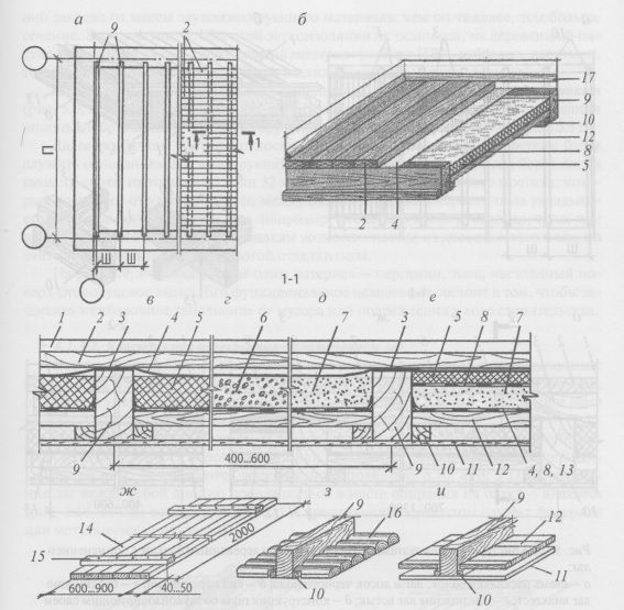
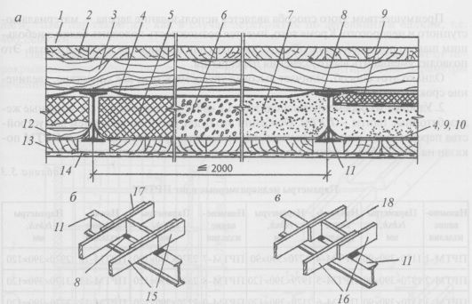
The design of the interfloor ceiling on wooden beams without the use of logs: a - layout of beams and subfloor boards; b - type of overlap; in-e- composition beam overlap layers; c - floor structure with a soundproofing layer of effective insulation; g - the same, from expanded clay; d - the same, from sand; e - two-layer sound insulation; g - shield reel; h, i - views decking; 1 - clean floor construction; 2 - black floor boards; 3 - soundproof elastic layer (for example, three layers of roofing material); 4 - rolled material that protects the inter-beam filling from scree, debris (for example, glassine); 5- effective insulation (mineral wool, expanded polystyrene); 6- expanded clay; 7- sand; 8- geotextile; 9-beam ceiling; 10-skull bar 30x40, 40x50 or 50x50 mm; 11 - ceiling decoration; 12 - floor boards; 13 - rolled material (roofing felt, roofing material, PVC or polyethylene film, etc.); 14 - rolling boards; 15- rolling bar; 16 - flooring slab; 17-plinth.
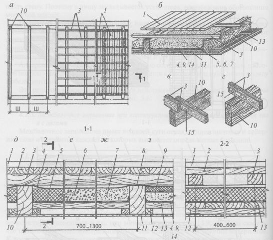
The design of the interfloor ceiling on wooden beams using a log: a - a diagram of the layout of beams, logs and subfloor boards; b - type of overlap; c - overlapping lag connection; g - butt-joint lag; e - floor construction with a soundproofing layer of effective insulation; e - the same, from expanded clay; g - the same, from sand; h - two-layer sound insulation; 1 - clean floor construction (conditionally shown); 2 - black floor boards; 3 - lag 50x75 mm, laid flat; 4-roll material that protects the inter-beam filling from scree, debris (glassine, roofing paper); 5 - effective insulation (mineral wool, expanded polystyrene); 6- expanded clay; 7- sand; soundproof elastic layer; 9 - geotextile; 10- floor beam; 11- ceiling decoration; 12 - cranial bar 30x40.40x50 or 50x50 mm; 13 - flooring boards; 14 - roll material (roofing felt, roofing material, PVC or polyethylene film, etc.); 15 - plywood or plank lining.
To support the inter-beam filling, a shield roll is also suitable. Fragments of the shield roll are prepared in advance, and then they are laid with support bars on the cranial bars; what it looks like is shown in the figure.
Further, subfloor boards are laid along the beams, which will subsequently serve as the basis for the construction of a clean floor. For the subfloor, low-grade boards are taken, their thickness is 25 or 32 mm. To eliminate the sound bridge that occurs from the shock wave, a soundproof lining is laid between the beam and the subfloor boards, for example, several layers of roofing material, roofing felt, or other elastic material. On the beams, flooring from clean floor boards is possible, but this option is not suitable for expensive flooring.
The figure shows another material - glassine, tar paper, laid on top of a layer of sound insulation. Its functional purpose is to protect the inter-beam filling from debris or damage during construction.
Floor construction using lag
As can be seen from the table, the step of the beams and their cross section are interrelated values: the more powerful the beams, the greater the step they can be laid. This is good, because the labor intensity decreases when embedding beams in niches. However, with a beam spacing exceeding 600 mm, floor rigidity will not be ensured.
Logs will help to increase the rigidity of the floor - boards with a section of 50x75 or 50x100 mm. Logs are laid flat across the beams or placed on edge, and black floor boards are laid on them, perpendicular to them. The connection between the logs should be made at the point of support on the beam - overlap or butt. The fastening element is a plywood or metal lining.
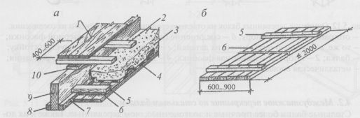
The design of the floor with lags and shield roll: a - type of floor; b - type and parameters of shield run-up; 1 - black floor boards; 2 - logs laid flat; 3 - soundproofing layer; 4 - roll material; 5 - bar of shield rolling; 6 - shield boards; 7- nails for fastening the cranial bar; 8 - cranial bar; 9 - beam; 10 - elastic material to eliminate the sound bridge.
The inter-beam filling is the same as in the design without a lag. At the same time, the lag also has another purpose: by increasing the height of the inter-beam space, more or thicker layers of soundproofing material fit. Soundproofing layers are laid on the flooring or shield roll.
Logs are arranged in increments of 400 ... 600 mm; at the same time, the regularity is observed: the larger the step of the beams, the smaller the step of the lag.
The logs are adjacent to the wall, but they are not embedded in the wall.
Supporting wooden beams on vertical supports
With a frame or combined structural system, floor beams are supported by free-standing supports: racks, columns, poles.
If it is necessary to connect the beams, it is necessary that the docking point is above the vertical support. If the supports are wooden, then the beams are attached to the supports with nails hammered at an angle and connected with brackets. Fastening can be done using plywood pads, which are fastened on both sides of the butt-joined beams. Various metal attachment points are also used, such as those shown in the figure. For round racks, the support area of \u200b\u200bthe beams may not be enough, then the lower faces of the butt-joined beams are bolted to a metal plate.
Logs are also joined above the supports.
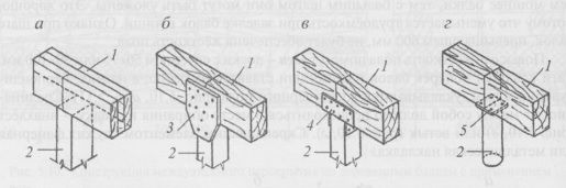
Supporting wooden beams on free-standing supports and methods for their connection: a - supporting the beam on the support; b - connecting the beams with a plywood gusset; c - the same, with the help of metal parts; g - beam support on a round post; 1 - beam; 2 - support; 3 - plywood gusset; 4 - detail of the metal fastening; 5 - metal platform of the column.
Interfloor ceiling on steel beams
Steel beams are stronger and more durable than wood beams. It is also fair to attribute to their advantages the ability to cover large spans - up to 7 ... 8 m. Such circumstances make steel beams more and more attractive in low-rise private housing construction, where there is a need for spacious rooms. Steel beams are widely used in the reconstruction of buildings.
It is interesting. in the Moscow Stalin skyscrapers, and there are, as you know, seven, reinforced concrete floors and with the use of steel beams. As surveys have shown, time has not damaged the floors, and they will stand for a very long time.
For steel beams, a rolled profile is suitable - I-beams, channels, corners.
The location of steel beams on the building plan is made from the same considerations as wooden beams. Therefore, the scheme shown in the figure is quite suitable for studying the nodes for embedding steel beams into the wall and inter-beam filling.
Embedding steel beams into the wall
Embedding beams in niches is similar to that in the case of wooden beams, but with some features.
Steel beams are embedded in niches specially prepared in the wall with a depth of 250 mm. To evenly distribute the forces, steel plates are laid under the beams, or the beams are laid on a distribution concrete pad. This technique also protects the wall of bricks or cellular blocks from crushing in the area where the beams are supported.
![]()
Embedding steel beams into the wall: a - an uninsulated niche, anchoring the beams with a steel strip or rod; b - insulated niche, anchoring beams with corners; c - embedding beams into a niche in the inner wall; g - view of an I-beam; 1 - symbol walls; 2 - cement-sand mortar; 3 - anchor - steel strip or rod; 4 - steel sheet to distribute the load from the beam; 5 - nabetonka with the same purpose; 6 - section "an I-beam; 7- I-beam; 8 - anchors - corners; 9 - effective insulation
The support depth of the steel beams must be at least 200 mm.
Finish a niche for the same reasons as in the case of wooden beams. If the niche device violates the heat-shielding properties of the wall, then a heater is laid between the back wall of the niche and the beam. In this case, the depth of the niche is calculated depending on the required thickness of the insulation.
The niche cavity is sealed with a cement-sand mortar. Unlike wooden beams, steel beams “feel good” when in contact with the mortar.
The beam is anchored into the wall using a metal anchor welded to the beam on one side and driven into the masonry on the other. In this case, the length of the bend must be at least 200 mm. For anchoring, corners welded to the beam from above and below and brought into the masonry will also fit.
The support of the beams on the inner wall, their anchoring and finishing of the niche is carried out in the same way as in the case of the outer walls.
Inter-beam filling
The step of the beams depends on the material of the inter-beam filling, namely the flooring on which the soundproofing layer is located.
Flooring - wooden shields. Shields are knocked down on the ground beforehand. Boards are knocked to the bottom of the bars, leaving the ends of the bars free. Then the bars with their free ends rest on the lower shelves of the I-beams, which play the role of cranial bars. The bars in the places of support on the beams are antiseptic.
Based on the characteristics of the work of the tree from which the flooring is knocked together, the step of the beams cannot exceed 2 m; the step of the beams is not subject to the module.
All other layers of inter-beam filling are the same as with wooden beams; the choice of the type of filling remains with the customer, who needs to be told all the pros and cons of this or that material.
To exclude contact with metal beams, subfloor boards must be insulated with wooden logs or some other insulating material. Logs are installed flat or on edge. The butt joint of the lag on the edge is made using a plywood gusset. For rigidity, a spacer is inserted between the lags. When overlapping, the logs go beyond the planes of the upper shelves of the beams. Spacers may also be needed here. Logs must be protected from contact with the metal of the beams; roofing felt, roofing felt, etc. are suitable for this.
Lags laid flat will allow you to slightly reduce the height of the ceiling.
The cross-sectional parameters of steel beams, as well as wooden beams, depend on the overlapped spans, steps, and loads. Approximate parameters of the section can be taken from the table.
The design of the interfloor ceiling on steel beams using shield roll: a - the composition of the layers of the floor structure; b - butt lag connection; in - the same, overlap; 1 - clean floor construction; 2 - black floor boards; 3 - logs 50x75, placed on edge; "/-roll material that protects the inter-beam filling from debris, scree; 5 - effective insulation; 6- expanded clay; 7- sand; 11 - steel I-beam No. 12 (only for this case study); 12 - a bar of shield rolling, based on the shelves of an I-beam; 13 - rolling boards; 14 - ceiling decoration; 15 - logs connected end-to-end; 16 - the same, overlapped; 17 - plywood gusset; 18- spacer.
Sections I-beams when using wooden shields
| beam profile number* | Section hxb, mm** | Span, mm | Pitch, mm*** | beam profile number* | Cross section xb, mm** | Span, mm | Pitch, mm*** |
|---|---|---|---|---|---|---|---|
| №10B1 | 100x55 | №16B1 | 157x82 | ||||
| №12B1 | 117x64 | №18B1 | 177x91 | ||||
| №14B1 | 137x73 | №20B1 | 200x100 |
* Data of the current range of rolled profile GOST 27772-88*.
*** The calculation of the step includes a payload on the ceiling of 200 kgf/m 2 , the mass of wooden panels and a soundproof layer of mineral wool boards with a density of 100 kg/m 3 . In the case of backfilling with expanded clay, the step is reduced by about 20%.
The advantage of this method is the use of wood - an affordable and inexpensive material. In addition, it is possible to lay beams with a small step, in which lags are not necessary to increase the rigidity of the floor. This will reduce the height of the overlap section.
However, this method is distinguished by high labor intensity and, as a result, an increase in construction time.
It is more convenient and more modern to use small-sized reinforced concrete slabs as flooring - PRTM. Especially it will be a good solution for the installation of ceilings in sanitary facilities, where leaks are possible. The type of plates PRTM is shown in the figure, and the name and their parameters are given in the table.
Parameters of small size slabs PRTM*
| product name | Parameters lxbxh, mm | product name | Parameters lxbxh, mm | product name | Parameters lxbxh, mm | product name | Parameters lxbxh, mm |
|---|---|---|---|---|---|---|---|
| PRTM-1 | 1170x390x90 | PRTM-4 | 1770x390x90 | PRTM-7 | 2370x390x120 | PRTM-10 | 2970x390x120 |
| PRTM-2 | 1370x390x90 | PRTM-5 | 1979x390x120 | PRTM-8 | 2570x390x120 | PRTM-11 | 3170x390x120 |
| PRTM-3 | 1570x390x90 | PRTM-6 | 2170x390x120 | PRTM-9 | 2770x390x120 | PRTM-12 | 3370x390x120 |
| PRTM-13 | 3570x390x120 |
The step of the beams cannot be taken arbitrarily, as in the case of a wooden deck: it will depend on the length of the slabs. Since the smallest slab has a length of 1170 mm (PRTM-1), then, accordingly, the smallest step of the beams will be 1.2 m. The mass of such a slab is only 65 kg, so the laying of these particular slabs is practiced in low-rise construction if it is not possible to use lifting and transport equipment.
An example of the layout of beams and slabs, as well as the composition of the layers of inter-beam filling are shown in the figure. Here the slabs are laid on the lower shelves of the beams. In this case, they are located ribs up. Plots that are not a multiple of the width of the slabs are monolithic.
Plates can also be laid on the upper shelves - ribs down.
Strictly speaking, PRTM slabs are able to take a significant load, which is clear from their name (designed for a heavy load). And to take the load, they are designed to be located with the ribs down. However, in a joist slab, the load falls on the beams, so we can put the slabs with the ribs up as an inter-beam filling.
A soundproof layer is laid on the PRTM boards. Then, since the step of the beams does not provide the rigidity of the subfloor, it is necessary to lay the logs. The lag step is the same as in the case of overlapping on wooden beams, i.e. 400...600 mm.
The parameters of the cross-section of the beams in the case of filling with PRTM slabs depend on the overlapped spans, steps and, of course, loads. Approximate parameters of the section can be taken from the table.
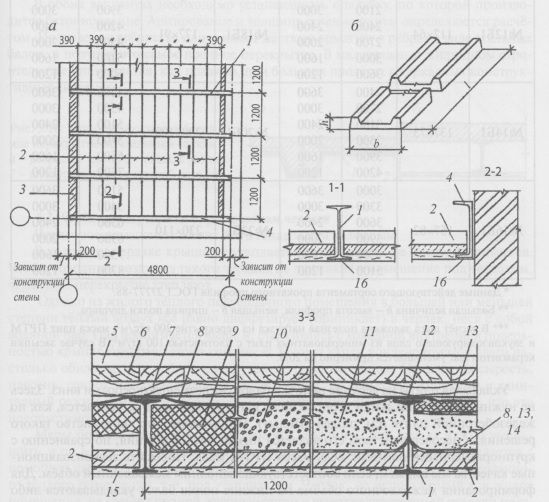
An example of a floor arrangement on steel beams using PRTM slabs: a - plan for laying out beams and PRTM slabs; b - type and parameters of the PRTM plate; 7 - I-beam No. 18 (only for this particular example); 2- plate P RTM-1; 3 - monolithic section; 4- channel No. 18; 5 - clean floor construction; 6 - black floor boards; 7-lags 50x75 laid flat; 8 - rolled material protecting the space between beams from scree; 9 - effective insulation; 10 - expanded clay; 11 - sand; 12 - soundproof elastic layer; 13- geotextile; 14-roll material (roofing felt, roofing material, PVC film, etc.); 15- ceiling decoration; 16 - metal mesh (when finishing the ceiling with plaster).
| beam profile number* | Section hxb, mm** | Span, mm | Pitch, mm*** | beam profile number* | Section hxb, mm** | Span, mm | Pitch, mm*** |
|---|---|---|---|---|---|---|---|
| №12B1 | 117x64 | №18B1 | 177x91 | ||||
| №14B1 | 137x73 | №20B1 | 200x100 | ||||
| №16B1 | 157x82 | №23B1 | 230x110 |
* Data of the current range of rolled profile GOST 27777-88.
** Large value h - profile height, smaller b - I-beam flange width.
*** The calculation of the pitch included the payload on the ceiling of 200 kgf/m 2 , the weight of the PRTM boards and the soundproofing layer of mineral wool boards with a density of 100 kg/m 3 . In the case of backfilling with expanded clay, the step is reduced by about 20%.
When laying the slabs on the upper shelves of the beams, they are placed with the ribs down. No logs or black floor boards are needed here: the floor structure is arranged as if on a reinforced concrete slab (see the "Floors" section). Undoubtedly, this is the advantage of such a solution, and its imperfection is low sound insulation, compared with large-sized slabs: after all, the mass of the PRTM is small. We will be able to improve the soundproofing qualities if we fill the inter-beam volume accordingly. To form an inter-beam volume, either wooden shields are laid on the lower shelves of the beams, if there is no more than 2 m between the beams, or slabs - gypsum fiber, glass-magnesium, calcium sulfate and others offered by the construction market. Any soundproofing layer is chosen - from environmentally friendly sand and expanded clay to synthetic effective heaters.
This option does not require a graphical explanation, therefore, by compiling all the above solutions, you will be able to independently develop a section of the interbeam space.
Monolithic reinforced concrete slabs on steel beams
Instead of prefabricated technology - laying PRTM slabs - a monolithic reinforced concrete floor can be arranged on steel beams. In this case, the steel beam is either concreted or remains open. In the second case, the beams are necessarily hidden by a false ceiling, in the first case - at the request of the customer.
In both options, it is necessary to install the formwork on which concreting is carried out. Reinforcement and thickness of the slab section are determined by calculation. The resulting ribbed slab has rigid reinforcement in the ribs in the form of steel beams, and therefore this is the most durable floor. In a low-rise housing construction it is used, as a rule, for large spans in frame structural systems.
Attic floor in cold attic
The attic can be warm or cold.
In a cold attic, the roof is not insulated, and heating is not provided. To prevent cold air from such an attic from penetrating into the room under the attic, the attic floor is insulated.
However, from a residential warm attic space, to a greater or lesser extent, warm air still diffuses (penetrates) into the attic, carrying water vapor with it. The steam rises higher and, colliding with the cold inner surface of the roof, turns into condensate. Sometimes the drops of condensed moisture are so plentiful that, gathering in streams, they flow along the walls. Dampness, mold, fungus and other phenomena appear that worsen not only the humidity and sanitary conditions of the house, but also destroy the structures of walls and roofs. It is clear that this is unacceptable.
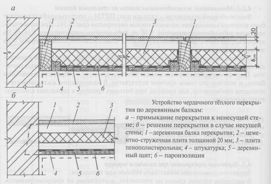
Measures to combat the appearance of condensate are different. First you need to reduce, and if possible, cut off the flow of steam into the volume of the attic. This is done with the help of vapor barrier materials laid from the side of the attic warm room, i.e. under the insulation. An attic that is not used as a living space does not require complete soundproofing and high-quality flooring, so some elements of the attic floor may not be laid in it. How one of the large design firms in Moscow solves this issue is shown in the figure.
If you want to make the attic floor the same as the interfloor one, you need to lay not any rolled material under the insulation (recall that in the usual interfloor floor it played the role of a barrier against scree of soundproofing material), namely vapor barrier.
If steam nevertheless penetrates through leaks in the structure or other ways, which most often happens, then constructive measures are taken: for example, air ducts are arranged to ventilate the roof, which will be discussed in the "Roofs" section.
With a warm attic, insulation is laid in the roof structure (for more details, see the "Roofs" section), and the attic floor is not insulated.
Basement (basement) ceiling above a cold room
A cold room can be an unheated basement or basement. Here the situation is similar to that with a cold attic. Water vapor, rushing into a cold room, condenses on the walls of the basement (ground floor) and the lower surface of the ceiling facing the basement room. A damp cold room will be completely unsuitable for any purpose. Another danger: in a damp room, wooden beams will quickly rot, and steel ones will rust; this is a question of an incorrect design solution, which reduces the durability of the floor.
Normal operating conditions in the basement ( ground floor) will be provided if:
- lay a vapor barrier layer from the side of the warm basement (above basement) premises, i.e. above the heater
- make vents around the perimeter of the house, giving air access to the basement for ventilation, if the basement is not completely buried in the ground (the smallest vent size is one brick). The vents are sealed with nets, and for the winter, if necessary, they are covered with something, such as bricks or special plugs.
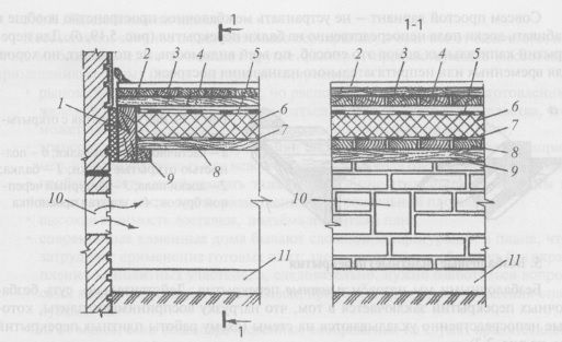
The device for overlapping on wooden beams above a cold room and ventilation of the room: 1 - a wooden floor beam; 2 - clean floor construction; 3 - black floor boards; 4- logs; 5 - vapor barrier; 6 - thermal insulation; 7-roll vapor-permeable material; 8 - boardwalk; 9 - cranial bar; 10 - air; 11 - floor construction on the ground.
In the case of an underground floor, i.e. when the basement is completely buried in the ground, ventilation ducts must be removed. This is already the question of engineering equipment at home, which is not considered in this book.
Beam ceiling finish
Finishing the ceiling ceiling is made depending on the design idea. Before that, we studied drawings in which the beams are hidden by some kind of trim or filing. For finishing, plaster, profiled natural board of the "lining" type, gypsum boards ("dry plaster"), special finishing ceiling tiles, etc. are suitable.
As for steel beams, they are almost always closed, because there is no beauty in them, unless, of course, the house is made in a certain style.
However, wooden beams often want to emphasize. In such cases, the cranial bars are knocked to the beams to the desired height. Moreover, the cranial bars can also be shaped. Ordinary bars are hidden by filing.
When accepting this option for solving the ceiling, one should not forget that the volume between the beams will decrease here, and, consequently, the sound insulation of the ceiling will suffer.
A very simple option is not to arrange the inter-beam space at all and fill the floor boards directly onto the floor beams. For floors of capital houses, this method, apparently, is not suitable, but it is good for temporary or unassuming buildings.
Beam ceilings are used in low-rise construction (in wooden and stone buildings), in the reconstruction of buildings old building by replacing wooden beams with more durable metal or reinforced concrete ones.
According to the material, the beams are divided into wooden, reinforced concrete and metal.
Ceilings on reinforced concrete beams. Ceilings on reinforced concrete beams consist of beams laid on load-bearing walls with a distance in the axes of 600, 800, 1000 mm, inter-beam filling and floor (Fig. 5.5).
The depth of support of the ends of the beams on the walls or girders is taken at least 150 mm. The ends of the beams on the supports are anchored, and the gaps between the beam and the nest walls to a depth of 40-60 mm are sealed with mortar. Inter-beam filling (Fig. 5.6) consists of a run-up, which is a flooring of lightweight concrete slabs and a soundproof (heat-insulating) layer. The seams between the rolling elements and the beams are carefully filled with mortar or glassine is laid on top of the rolling. Soundproofing is usually performed from a layer of slag or sand with a thickness of at least 60 mm. From below, the roll and beams are rubbed with mortar. This design is used for plank floors along the logs. When installing other types of floors, such as cement, requiring a continuous gesture
Fig.5.5. Prefabricated reinforced concrete beams and details of their support:
a - plan for the location of floor beams; b - general view of the beam; 1 - beam;
2 - steel anchor; 3 - steel structure; 4 - mounting loop; 5 - concrete embedment
After some preparation, the space between the beams is filled with slag, along which a layer of cinder concrete with a thickness of at least 40 mm and a floor are laid (Fig. 5.6d). More appropriate in these cases are rolls of double-hollow lightweight concrete stones - liners that have sufficient soundproofing properties and require only careful filling of the joints with mortar (Fig. 5.6 e).
Ceilings on metal beams. Currently, metal beams are used only in exceptional cases in the repair and reconstruction of buildings.
Steel beams (usually I-beams) are located at a distance of 1-1.5 m from each other. The depth of support of their ends on the walls is 200-250 mm.

Fig.5.6. Prefabricated beam construction
reinforced concrete elements:
a - general view; b - lightweight concrete slab; c - lightweight concrete stone insert; d, e - floor options with mineral floors; 1 - reinforced concrete beam; 2 - reel from lightweight concrete slabs; 3 - waterproofing layer; 4 - sound insulation; 5 - soundproof gasket; 6 - log; 7 - plank floor; 8 - slag; 9 - slag concrete thickness
40 mm; 10 - cement floor 20 mm thick; 11 - grouting with mortar
To increase the area of pressure on the masonry in order to protect it from collapse, concrete pads or steel linings are placed under the ends of the beams. The ends of the beams are anchored into the masonry of the walls and, if necessary, insulated with felt, followed by sealing the gaps around the perimeter of the nest with concrete (Fig. 5.7).
Inter-beam filling can be made of reinforced concrete prefabricated or monolithic slabs, and in some cases from brick vaults.
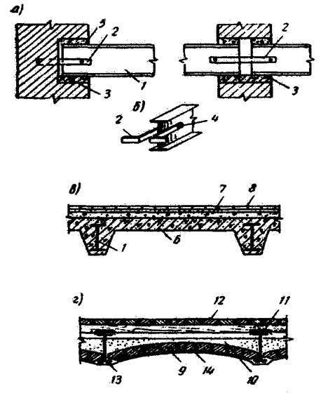
Fig.5.7. Ceiling construction on steel beams:
a - supporting the ends of the beams on the walls; b - anchor fastening detail; c - overlap with filling with a reinforced concrete monolithic slab; g - the same, brick vaults;
1 - steel beam; 2 - steel anchor; 3 - concrete pad; 4 - bolt; 5 - sealing with cement mortar; 6 - reinforced concrete monolithic slab; 7 - lightweight concrete; 8 - ceramic tiles over a layer of cement mortar; 9 - brick vault; 10 - soundproof layer; 11 - two layers of roofing; 12 - plank floor along the logs; 13 - steel mesh; 14 - plaster with cement mortar
Ceilings on wooden beams. At present, wooden floors are allowed only in low-rise buildings and only in areas where wood is a local building material. Their advantages are the simplicity of the device and the relatively low cost. Disadvantages - combustibility, the possibility of decay and relatively low strength.
All wooden floor elements are made from coniferous forests (pine, larch, spruce, etc.). Beams are made mainly in the form of rectangular bars, the dimensions of which are established by calculation. (Fig. 5.8). The distance between the axes of the beams is taken from 600 to 1000 mm.
To support the inter-beam filling, bars with a section of 40 x 50 mm, called cranial, are nailed to the sides of the beams (Fig. 5.8). The depth of support of the ends of the beams in the sockets of the stone walls must be at least 150 mm (Fig. 5.9). The ends of the beams are antiseptic with a 3% solution of sodium fluoride or coated (except for the ends) with resin, and when embedded in the outer walls, they are additionally wrapped with two layers of roofing paper. On internal walls or runs under the ends of the beams, two layers of roofing felt on tar mastic are laid. The gaps between the walls of the nest and the ends of the beams to a depth of 40-60 mm are tightly sealed with mortar. The location of the wooden floor beams, as well as their anchoring, are similar reinforced concrete floors beam type (Fig. 5.1 c).
The filling between the beams (Fig. 5.10) consists of a shield board run, lubrication on the top of the run with a clay-sand mortar 20-30 mm thick and a soundproof layer of slag or calcined earth 60 mm thick. The floors are made of boards along the logs with a device in them at the corners of the premises of metal ventilation grilles. Ceilings are plastered with lime-gypsum mortar along the strips or hemmed with sheets of dry plaster.
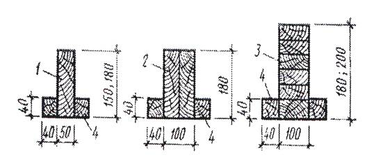
Fig.5.8. Constructive decisions wooden beams:
1 - bar single beam; 2 - beam composite of two bars of solid wood; 3 - a beam of glued wood; 4 - cranial bar
Rice. 5.9. Details of supporting wooden floor beams on
stone walls:
a - on the outer wall; b - on the inside; 1 - external load-bearing wall; 2 - external self-supporting wall; 3 - internal load-bearing wall; 4 - wooden beam; 5 - thermal insert; 6 - two layers of roofing paper on tar mastic or antiseptic zone of the beam; 7 - an anchor made of strip iron; 8 - crutches or nails
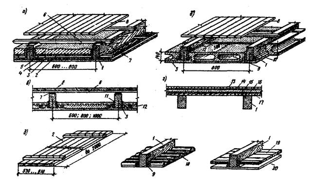
Fig.5.10. Floor construction on wooden beams:
a - with a plank shield roll; b - the same, from hollow blocks; c - the same, from lightweight concrete blocks (slabs); d - floors in bathrooms; e - types of rollovers; 1 - beams; 2 - reel (shield); 3 - plaster; 4 - clay lubricant; 5 - backfill; 6 - log; 7 - soundproof gasket; 8 - plank floor; 9 - hollow lightweight concrete block; 10 - cranial bar; 11 - solution; 12 - gypsum board; 13 - ceramic tile floor; 14 - cement screed 20 mm; 15 - concrete preparation; 16 - two layers of roofing material on mastic; 17 - plank floor; 18 - plates; 19 - boards; 20 - false ceiling
