Frame industrial buildings. One-story industrial buildings. Reinforced column grid
The predominant type of industrial buildings are one-story (approximately 64% of all industrial buildings). This is explained by the requirements of the technology, the ability to transfer loads from heavy equipment directly to the ground, and the comparative simplicity and cost-effectiveness of their construction.
Structural elements of one-story industrial buildings, both in their forms and functional features, differ significantly from those used in residential and public buildings. Such buildings are usually erected as frame buildings with curtain wall panels made of lightweight concrete or other materials.
The structural designs of one-story industrial buildings are varied: the most common are single-span and multi-span frame designs with a coating system (flat and spatial) in the form of domes and cable-stayed structures. Coverings are made flat or pitched, with lanternless or lantern superstructures. Single-story multi-span frame buildings They come with spans of the same or different widths and heights or single-span. A span is an internal volume bounded by two rows of columns and end walls.
Depending on the type of materials used, frame structures can be reinforced concrete or steel. Reinforced concrete frames can be monolithic or made from standard prefabricated reinforced concrete elements of factory production.
 |
|
 |
|
 |
|
|
Structural diagram of the frame of a one-story industrial building: a - steel; b - reinforced concrete; c - wooden; 1- columns; 2- farms; 3- crane beams; 4-runs on farms; 5-horizontal connections across farms; 6- vertical connections between trusses; 7- lantern frames; 8-horizontal lantern links; 9- lantern runs; 10- vertical connections of the lantern; 11- vertical connections along columns; 12-reinforced concrete lantern structure; 13- single-branch column; 14- two-branch column; 15- covering plate; 16-walls; 17-foundation; 18-wooden glued beam; 19- overhead crane; 20-two-branch metal-wooden column; 21-wood laminated column |
|
The frame of a one-story building with a covering of flat elements consists of transverse frames formed by columns clamped in the foundations and trusses or beams hinged on the columns.
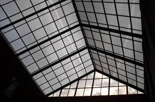
The frames are installed at a distance of 6 or 12 m from each other. The longitudinal elements of the frame are supported on the frames: crane beams, along which paths are laid for overhead cranes, a wall frame crossbar (half-timbered frame), used for fastening window sashes and wall enclosing panels in case of vertical cutting; reinforced concrete roof panels or steel roof purlins, on which profiled steel sheets or panels are laid asbestos cement sheets and other materials; lanterns, the purpose of which is to provide natural aeration and lighting of buildings.
In the longitudinal direction, the frames are connected by crane beams, spacer beams, rafter trusses, a rigid coating disk and, if necessary, steel ties. HDD form slabs welded to trusses or beams with subsequent monolithic seams. Flat structures span spans up to 36 m.
Reinforced concrete wall panels are attached directly to the frame columns; lightweight metal or asbestos-cement panels are attached to steel beams or other wall framing members attached to columns.
In connection with the mass production of standardized 6-m wall and window panels, the 6-m step is more often adopted in the outer rows of columns. In order to efficiently and maneuverably use production space in the middle rows of columns, the 12th step is most common.
The spans of one-story industrial buildings are taken to be 12, 18, 24, 30 and 36 m for workshops with crane loads and from 12 to 48 m or more for workshops without cranes.
Prefabricated reinforced concrete columns can be solid rectangular or two-legged.
 |
 |
 |
|
|
Frame diagrams for one-story industrial buildings a - with a flat roof; b - with a pitched roof and lanterns; 1 - fundamental beams; 2 - foundations; Z - columns of the outermost row; 4 — columns of the middle row; 5 — crane beams; 6 — covering beams; 7 — covering panels; 8 — drain funnel; 9 - insulation and roofing; 10 - parapet; 11 - wall panels; 12 - window sashes; 13 — floor; 14 — lantern; 15 - roof trusses |
|
Single-story industrial building can have simple and complex shapes in plan.
Currently, the rectangular shape with large building dimensions in plan (continuous development) is also predominant, eliminating the indicated disadvantages of separate development of the territory with small buildings.
Buildings of complex shapes: U-shaped, W-shaped and comb-like, similar to W-shaped ones, are used only for aerated workshops with large heat and gas emissions (rolling, pressing, forging and similar shops), since the developed perimeter allows organizing the influx and removal of air. To ensure ventilation of dead-end courtyards, their width must be at least half the sum of the heights of opposing buildings, but not less than 15 m (in the absence of harmful emissions, this value can be reduced to 12 m). Dead-end yards are located parallel to or at an angle of 0-45° to the prevailing wind direction. The open side of the yard is turned to the windward side, and if, according to the planning conditions, such an arrangement is impossible, aeration openings of at least 4 m wide and 4.5 m high are installed in the closed side.
Depending on the characteristics of the technological process, one-story industrial buildings according to the space-planning solution can be span, hall, cell and combined type.
Span-type buildings are used in cases where technological processes are directed along the span and are serviced by cranes. Span sizes of 12-36 m are selected depending on the nature of the technological process, the dimensions of the equipment and products being placed. The pitch of internal vertical supports (columns) is usually 6 or 12 m, maybe more, but in all cases a multiple of 6 m.
Transport connections between individual sections in span-type buildings are achieved using overhead and overhead cranes, conveyors or floor transport.
Unified standard sections(UTS) and unified standard spans were used in the design of pavilion-type industrial buildings, both continuous buildings and in the form of separate buildings. By blocking standard sections and spans, it was possible to obtain various space-planning solutions for buildings.
The varied dimensions of the standardized sections and spans made it possible to assemble them into continuous industrial buildings for various purposes and large area, which made it possible to place in them not only individual workshops of one enterprise, but also different industrial enterprises. UTS were divided into crane and craneless.
For mechanical engineering enterprises, the dimensions of the main types of technical equipment are 72x72 and 144x72 m. For assembly and warehouse shops at mechanical engineering enterprises, there is a need to construct longitudinal and transverse spans. In these cases, additional sections are used, the length of which is 72 m and the width is 24, 30, 48 and 60 m with one or two spans.
There are longitudinal and transverse zoning. Zoning of production areas ensures more rational use of building volume. It is advisable to locate workshops (departments) with large heat and gas emissions, fire and explosion hazardous processes near the outer walls of buildings, since this makes ventilation and ejection structures in the event of an explosion easier and more economical. It is advisable to locate production facilities that require air-conditioning in the middle part of the building.
Single-story industrial buildings span type may have a complex shape in plan. When individually designing for one-story industrial buildings of a span type, the following dimensions of the column grid are often used:
- in craneless buildings without suspended equipment and with suspended lifting and transport equipment with a lifting capacity of up to 5 tons inclusive: 12X6, 18×6.24×6, 18×12, 24x12 m. A 12×6 m mesh is used in small buildings;
- in buildings equipped with overhead cranes with a lifting capacity of up to 50 tons inclusive: 18X12, 24X12, 30X12 m. When designing, it should be taken into account that an enlarged grid of columns allows for more economical use of the production area. The optimal column grid for most industries is 18X12 or 24x12 m.
 The most commonly used industrial hangar-type buildings. They are a set of standard modules, locked for a device of a specific manufacturer.
Most often, hangar-type buildings are used in the construction of: industrial workshops and buildings; warehouse complexes, hangars and terminals; covered markets and exhibition complexes; sports facilities; supermarkets and pavilions; parking lots and service stations; rotation camps; buildings and canopies for gas station complexes.
As a rule, one-story hangar-type buildings are used single-span and multi-span, without crane equipment and with cranes with a lifting capacity of up to 50 tons.
Hangar building, as a rule, has a large span (reaching 100-150 m). The space-planning scheme of the building also predetermines its design solution. Thus, U-shaped, L-shaped and through blocking schemes are accepted for spans up to 100 m with a transverse arrangement load-bearing structures; for spans up to 150 m, a transverse-longitudinal arrangement of structures can be used, and with a linear one-sided or two-sided blocking and T-shaped scheme, cantilever load-bearing structures can be used.
When choosing a blocking scheme and solutions for load-bearing structures, the future prospects for the development of aircraft manufacturing, the specialization and specifics of enterprise expansion, as well as the conditions of typification, unification and economics are taken into account. The most technologically flexible and economical are linear one-sided, L-shaped and end-to-end blocking schemes.
Hall type buildings- these are long-span one-story buildings without intermediate internal supports; they are used in cases where the technological process is associated with the production of large-sized products or the installation of large-sized equipment: machine rooms of thermal power plants, hangars, aircraft assembly shops, main buildings of open-hearth and converter shops, etc. P.
Hall type buildings get in Lately distribution in industries in which the technological process is not associated with the production of large-sized products or the installation of large-sized equipment. This is explained by the fact that the large size of production premises allows free use of space and placement of any technological processes.
Building spans hall type may be 100 m or more. Such spans are usually covered with spatial structures. There are longitudinal and transverse arrangements of halls in the building. For aircraft assembly shops, a span of 60 m is quite appropriate, as it allows the assembly of aircraft with a wingspan greater than 60 m. In this case, the aircraft are placed on the conveyor at an angle to the longitudinal axis of the flight.
Hall-type buildings used for chemical industry enterprises with an enlarged grid of columns (24x12 or 30x12 m) allow them to accommodate multi-story prefabricated shelves for placing process equipment. In such buildings it is easy to modernize equipment, change the technological process, introduce new technology without rebuilding the main structures of the building.
Hall-type buildings with prefabricated shelves have lighter floors than multi-storey buildings, which reduces the weight of the building and, consequently, the cost of construction.
Frequent modernization of the technological process is easier to carry out in one-story continuous buildings with a square grid of columns. This structure of the space-planning solution is called cellular; buildings are called flexible or universal. In cellular-type buildings, the most common column grids are 12x12, 18x18, 24x24, 30x30 and 36x36 m.
A larger column grid makes it easy to change the placement of equipment and the direction of process flows. In flexible workshops, the height of all spans is assumed to be the same, and overhead cranes, conveyors or floor-mounted transport are used as lifting and transport equipment. In flexible workshops, significant changes in the technological process do not affect the building structures, i.e. its space-planning and design solution remains constant. In addition, technological flexibility of production, unification of space-planning and design solutions, increased efficiency of use of production space, and reduced construction costs are achieved.
Flexible buildings are most widespread in the engineering industry (machine tool, tractor, automobile, etc.).
The useful area of flexible workshops is intended only to accommodate technological and transport equipment (conveyors, roller tables, etc.) of the main production process. Auxiliary premises that do not require great height are placed on mezzanines, in the inter-truss space or in extensions. Mezzanines are usually located near the outer walls of a building or on the border of workshops with different production modes or between enterprises that are part of one building. Mezzanines are installed above utility and production premises, intra-shop passages and in the “dead” zone of crane equipment operation. The structural design of mezzanines is most often framed with a grid of columns 6x6 m in prefabricated structures.
Cellular buildings are designed with natural and artificial lighting. To illuminate production areas in flexible workshops, so-called “floating” overhead lighting systems are used, the location of which does not depend on the size of the spans. The use of such systems makes it possible to obtain uniform illumination over the entire area of the workshop.
In buildings of a combined type, as the name suggests, the space-planning solution can combine the features of buildings of span and hall types, span and cellular types, etc.
CHAPTER 9. INDUSTRIAL, FRAME AND LARGE-PANEL BUILDINGSSummary:
This section examines the most widely used frame structures and large panel industrial buildings. general information about them is presented, detailed information about multi-story industrial buildings is attached.
9.1. General information.
Industrial buildings (hereinafter referred to as P.Z.), industrial buildings industrial enterprises, buildings designed to house industrial production and provide the necessary conditions for human labor and operation of technological equipment.
How independent type buildings P. z. appeared in the era industrial revolution, when there was a need for large premises for machines and numerous workers. First P. z. were rectangular in plan, with load-bearing brick or stone walls and wooden floors Purely utilitarian solutions prevailed: an extended array of unplastered walls was often divided only by pilasters and was decorated with belts of figured masonry. Sometimes in exterior decoration P. z. decorative elements of various architectural styles were used.
With the development of construction technology and the emergence of such new building materials, like metal and reinforced concrete, frame structures were developed, which made it possible to abandon traditional compositional schemes and create a rational layout of workshops in accordance with the requirements of production technology. Application since the end of the 18th century. in the construction of P. z. a frame made of cast iron posts and beams made it possible to build less massive walls, increase the number of storeys and the size of light openings, which immediately had a noticeable impact on the appearance of the building. The appearance of the building in the early 19th century. floors made of metal trusses and their subsequent improvement made it possible to create large spans with sparse supports that do not interfere with the installation of equipment
In the 1930s-60s. in the construction of P. z. New structural systems are being widely introduced, making it possible to span large spans without supports, and new construction and finishing materials are being used. In the conditions of the modern scientific and technological revolution with constant technical progress in the construction of landfills. and the improvement of production technology, the number of enterprises that do not have a harmful impact on the environment is growing. As a consequence of this, a new type of development is being created - industrial and residential. Having their own large scale, volumetric-spatial solution and silhouette that differs from standard residential buildings. P. z. become important architectural accents in the composition of urban development.
The role of scientists in the formation and development of architectural science and practice is great, which has dramatically improved last years quality and expressiveness industrial facilities. The works of scientists of the Republic of Uzbekistan (Umarov A.A., Valiev R.M., etc.) significantly influenced the development of architecture and urban planning with an industrial zone.
As follows from the works of scientists, the architectural image of P. z. to the greatest extent depends on how clearly the typological features of this type of structure are expressed in its appearance, its characteristic features: huge sizes and significant length of facades, large continuous planes of blank walls and glazed surfaces corresponding to a single undivided internal space, repeatedly repeated ends of parallel spans , elements of coatings (comb, sawtooth or curved outlines), staircases, etc., the presence technical devices(smoke and ventilation pipes, pipelines, open equipment, etc.). It has a great influence (especially with industrial construction methods) on the appearance of the land. artistic expression of the tectonic properties of the materials and structures used, as well as the texture and color of structural and finishing materials.
A noticeable role in the appearance of P. z. In the Republic of Uzbekistan, sun protection devices are used - the so-called. sun cutters, visors, decorative grilles. Great importance to improve the aesthetic qualities of P. z. has a clear internal layout, rational proportions and divisions of individual rooms and a plastic solution to them structural elements, zoning of production premises with systematic placement of main technological equipment, intra-shop communications, passages and driveways, color scheme interiors, consistent implementation of a set of activities related to the requirements technical aesthetics. P. z . and structures have a huge (often negative) impact on natural and architectural landscapes; Industrial areas often lose touch with the natural environment. Therefore, industrial architecture is faced with the task of maximizing the preservation of the natural landscape and the harmonious inclusion of new landscapes into the landscape.
On the formation of types of P. z. The decisive influence is exerted by socio-economic conditions and scientific and technological progress in industrial production technology and construction equipment. In the USSR and other socialist countries, the nature of the social system determined the emergence of P. z. a new type, which embodied the achievements of social and scientific and technological progress. Development and improvement of architectural and construction solutions P. z. based on scientific research, which determined the main directions of modern industrial construction, which provide for: ensuring the universality of production facilities, that is, the possibility of the most flexible use of production space when changing technological processes; unification of space-planning and design diagrams PZ, which allows for the fullest use of the production base of the construction industry; maximum blocking (consolidation) of workshops and entire production facilities in enlarged buildings.
9.2. Reinforced grid of columns.
The versatility of P. z. is achieved by using enlarged grids (spans and steps) of columns and a uniform height of rooms within each building, as well as the use of prefabricated partitions and dismountable partitions to accommodate the main equipment whatnot, providing the opportunity to modernize technological processes with a minimum amount of work on reconstruction of the building. Unification of space-planning and structural schemes of PZ. allows you to significantly reduce the number of standard sizes of products and structures, create the necessary conditions for their mass factory production and widespread implementation in construction practice. In the USSR, an intersectoral unification of the main construction parameters of residential buildings was carried out: grids of columns, floor heights, dimensions for linking structural elements to modular alignment axes, etc. Dimensions of grids of columns of single-story P. Z. accepted as multiples of 6 m, the size of the spans of multi-storey residential buildings -3 m, column pitch - 6 m. Height of floors P. z. multiple of 0.6 m. Blocking P. z . (cm. Blocked industrial building) - one of the most effective means reduction estimated cost construction of P. z. The greatest reduction in capital costs due to blocking (compared to separately constructed workshops) is achieved in cases where there is no need to isolate workshops from each other with capital walls, level the heights of adjacent rooms in order to unify structures, arrange additional intra-shop passages or increase the area of areas served heavy-duty cranes.
P. z. are distinguished according to the following main characteristics: by number of storeys (the main classification characteristic) - into one-story, two-story, multi-story; for lifting and transport equipment - cranes equipped with overhead (electric) and overhead (electric or manual) cranes, and craneless; by appearance lighting- for buildings with natural lighting (side and top), with constant working artificial lighting (windowless and lanternless) and buildings with combined lighting (combining natural lighting with artificial); for air exchange systems - for buildings with general natural ventilation(aeration), with mechanical ventilation and with air conditioning; according to the temperature regime of industrial premises - heated and unheated. According to the capital of P. z. are divided into 4 classes depending on the purpose of the buildings and their economic significance.
One-story residential buildings - the most common type of buildings for industrial enterprises. Their share in the total volume of modern industrial construction is 75-80%. One-story residential buildings They are usually used to accommodate industries with heavy technological and handling equipment or those associated with the manufacture of large, bulky products, as well as industries whose operation is accompanied by the release of excess heat, smoke, dust, gases, etc. Single-story buildings. create favorable conditions for the rational organization of the technological process and modernization of equipment; they allow the foundations of heavy machines and units with large dynamic loads to be placed directly on the ground; they provide the possibility of uniform lighting and natural ventilation of rooms through light and aeration devices in the coating.
9.3. One-story frame buildings.
Reinforced concrete frames of one-story buildings (industrial, agricultural, etc.) consist of columns and rafter beams, trusses and arches, and, if necessary, of crane and strapping beams, etc. all the main loads in such buildings are transferred to the frame, and the walls are self-supporting . In some cases, structural designs of buildings with an incomplete frame are used, in which load-bearing walls (usually with pilasters) are provided instead of the outer rows of columns. Reinforced concrete frames of buildings should be designed from prefabricated standard elements with spans of 6, 12, 18, 24, 30, 36 m, column spacing of 6 and 12 m. Preference should be given to enlarged column grids of 1224, 1230 m, etc. In buildings with overhead cranes, rectangular and two-branch columns with consoles for crane beams are used.
In craneless buildings, rectangular columns without consoles are used. Reinforced concrete columns are rigidly embedded in glass-type foundations. The frame crossbars, which are a rafter beam, truss or arch, are supported on top of the columns.
The most industrial types are used for wall filling of the building frame. wall structures– reinforced concrete wall panels with a length equal to the pitch of the columns, i.e. 6 and 12m. in heated buildings, insulated panels are used, which can be two-layer (reinforced concrete ribbed panel filled with lightweight porous concrete) or single-layer made of lightweight reinforced concrete, reinforced foam concrete, etc. The panels are attached to the columns with bolts or welding of embedded parts.
Technical and economic analysis shows that one-story buildings with prefabricated reinforced concrete frames are more economical than buildings with steel frames. Thus, with a grid of columns of 624 m, the consumption of steel per 1 m 2 of building area is reduced by 2.5 times only due to the replacement of steel trusses with prestressed reinforced concrete ones.
One-story industrial buildings.
Types of one-story frame buildings
Industrial buildings are mainly designed and erected as one-story buildings (about 70%). Such buildings house production facilities with heavy and bulky equipment that cannot be placed on the floors multi-storey buildings, since they turn out to be too powerful and uneconomical. The conditions for placement and operation of equipment, as well as the need to change the technological process in the future, require a coarse grid of columns and a high building height. In many cases, single-story buildings are equipped with overhead overhead cranes of significant lifting capacity, which create large forces in the load-bearing elements of the building. One-story buildings are widespread in metallurgical, mechanical engineering, and other industries.
There are the following types of one-story industrial buildings: single-span and multi-span; buildings without overhead cranes (50%), with suspended (15%) and with overhead cranes (35%); buildings with lanterns and without lanterns; buildings with pitched and slightly sloped roofs. It is recommended to design one-story industrial buildings rectangular in plan, with equal spans, without height differences to avoid snow bags. The question of choosing the material for the supporting frame should be decided on the basis of a technical and economic analysis. The main material for one-story buildings is precast reinforced concrete. Buildings are erected from it for 85% of production areas, while from metal - only 12%, and from other materials - for 3%. Steel load-bearing structures are recommended for use for large spans and building heights, in buildings with heavy crane equipment, when it is necessary to install overhead cranes in two tiers, and during construction in remote areas.
Building layout. Frame buildings are designed with mandatory compliance with modular dimensions adopted on the basis of the Unified Modular System. For industrial buildings, a span of up to 12 m is taken as a multiple of 3.0 m, and for a larger span – a multiple of 6.0 m. The height of the premises is set as a multiple of 0.6 m for a height of up to 6 m and a multiple of 1.2 m for a height of more than 6 m. The column spacing is 6 and 12 m. Not only volumetric planning parameters are unified: span, column spacing, room height, but also their combinations, called unified dimensional diagrams.
The main load-bearing elements of a frame one-story building are cross frames, which absorb loads from the mass of the coating, snow, cranes, wind pressure on the longitudinal walls and ensure the rigidity of the building in the transverse direction. The transverse frame of a building consists of columns embedded in the foundations or block part of the building, and a roof beam (beam or truss) resting on the columns.
Columns are usually connected to foundations rigidly, and crossbars to racks are usually connected rigidly or hingedly. For prefabricated structures, a hinged connection is more often used. In this case, the load applied to one of the elements does not cause bending moments in the other. This makes it possible to independently type the crossbar and columns, simplifies the design of the joint and allows for mass factory production of elements. As a result, the designs of single-story frames with hinged units turn out to be more economical, despite the fact that the forces in them are greater than with a rigid connection of elements. Structurally, the connection of the crossbar with the column is carried out using anchor bolts and assembly welding of the support sheet of the crossbar with the embedded part in the column.
Dividing the building into temperature blocks. Due to the large size of industrial buildings in plan and the continuity of the coating, which is a single rigid slab, changes in outside air temperature cause noticeable deformations (elongation and shortening) of transverse and longitudinal crossbars, crane beams, etc. Shrinkage of concrete leads to similar deformations, causing shortening of elements . These deformations cause significant additional forces to occur in the columns, which can cause the formation of excessive cracks and destruction of some elements. To reduce this kind of effort, the structures provide for temperature-shrinkage joints, arranged on paired columns with the seam reaching the top of the foundation.
If the distance between the seams does not exceed certain values, and the roof beams belong to category 3 in terms of crack resistance, then calculations for temperature effects may not be made. In this case, the maximum permissible distance l td between the joints is 72 m in heated one-story industrial buildings made of precast reinforced concrete, and 48 m in unheated ones. In some cases, it turns out to be advisable to calculate the frame for temperature effects and increase l td. This provides savings by reducing the number of transverse frames. Temperature t and shrinkage sh deformations within the block are calculated using the formulas:
T = b l td t 0 ; sh = sh l td ,
Where b is the coefficient of linear temperature deformation of concrete, equal to 1. 10 -5 1/deg; sh - linear shrinkage coefficient of concrete, equal to
15 . 10 -5 ; t 0 – maximum calculated temperature difference.
The forces in structures caused by these deformations are determined by methods of structural mechanics. In cases where a building is being erected on a site with heterogeneous soils, as well as when its parts have different heights and their uneven vertical displacement is possible, sedimentary joints are installed. They cut the building, including the foundations, to provide parts of the building with independent settlement. Settlement seams are usually combined with temperature-shrinkage seams.
Ensuring spatial rigidity of the frame. The spatial rigidity of a building or structure is its ability to resist horizontal loads. Ensuring spatial rigidity is important, since excessive movements of the frame can lead to disruption of the normal operation of the building (operation of cranes, etc.). The spatial rigidity of the frame of a one-story industrial building in the transverse direction is ensured by the calculation and design of the transverse frame. This is explained by the fact that special connections in this case cannot be established, since they would interfere with the technological process. Therefore, the main factors ensuring transverse spatial rigidity are pinching of columns in foundations and sufficient bending rigidity of columns. The spatial rigidity of the building in the longitudinal direction and the perception of longitudinal horizontal loads (wind pressure on the end of the building, the longitudinal force of the crane) are provided by the longitudinal frames of the building. These include cross frame columns, foundations, floor slabs, crane beams and vertical braces.
Vertical connections are installed along the covering elements and along the columns. Along the covering elements, connections are placed in the outer spans of the temperature block along the longitudinal axes at the level of the supporting parts of the supporting structures of the covering. With a pitched roof and a height of the supporting part of the crossbar up to 900 mm, you can not install ties. Vertical connections along the columns are installed in the middle of the temperature block. In craneless buildings with a height from the floor level to the bottom of the supporting structures up to 7.2 m inclusive, vertical connections along the columns are not installed.
Reinforced concrete construction beams and covering slabs
Reinforced concrete construction beams are used to cover spans of 6,9,12 m. With spans of 24 m or more, they are inferior to trusses in technical terms - economic indicators and are usually not used. Beams with spans of 6 and 9 m are intended primarily for covering. Beams with a span of 18 m are used as transverse crossbars, on which 3x6 or 3x12 m slabs are laid. Depending on the roof profile, beams can be gable, single-pitch, with parallel flanges, with a broken or curved outline of the top flange. Gable beams have an upper flange slope of 1:12 for pitched roofs, 1:30 for slightly sloping roofs. Due to their cost-effectiveness, they are most often used for covering spans of 18 m. Certain difficulties in their manufacture are associated with the construction of frames of variable height. If it is necessary to pass communications at the covering level (air ducts, etc.), gable lattice beams with a span of 12 and 18 m are used. Single-act beams are usually used for roofing with a one-sided slope, for example, in extensions.
Beams with parallel flanges are the easiest to manufacture and have reinforcement cages of constant height and are used as longitudinal crossbars for horizontal roofs. However, in terms of consumption of concrete and reinforcement, they are inferior to gable ones. Beams with a broken and curved top flange, despite being economical, have not found widespread use due to the complexity of their manufacture. The height of the section of beams in the middle of the span (1/10...1/12)l.
In order to save concrete, the cross-section of the beams is crushed using a T-bar
(at l = 6; 9 m) and I-beam (l = 12; 18 m). The width of the upper flange of the beams from the condition of feathering the covering slabs and ensuring stability during transportation and installation is taken equal to 1/50..1/60, which is usually 20..40 cm. The thickness of the vertical wall in the middle part of the span (6...8 cm) is determined based on the conditions of manufacturing the beam (in a vertical position) and the placement of transverse reinforcement (one or two frames).
Cover beams are made from heavy concrete of classes B25...B50 and from concrete with porous aggregates of classes B25...B40. Basically, prestressed structures reinforced with high-strength rods, single high-strength wire or bundles of it are used, and seven-wire ropes are also used. Beams are manufactured at factories of building materials and structures with reinforcement tensioned on stops.
Typical beams with a solid I-beam cross-section and lattice beams are designed with several options for reinforcement with longitudinal prestressing reinforcement of classes A - IV, A-V, A-VI, BP-II and K-7. Beams are designed for uniformly distributed loads from their own weight, the weight of the roof and snow, as well as concentrated forces from the weight of the lantern and suspended transport, if there is one in the building, taking into account the most unfavorable combination of loads.
Reinforced concrete roof trusses
Reinforced concrete roof trusses are used as crossbars for coverings of industrial and public buildings with spans of 18, 24, 30 m, pitch 6 and 12 m. With large spans, reinforced concrete trusses are heavy, inconvenient for transportation, labor-intensive to install, and can only be used with special justification. The outlines of the building trusses depend on the roof profile and the general layout of the covering. In terms of material consumption, segmental trusses with a curved or broken upper chord are the most rational, since their outline largely coincides with the diagram of moments from the external load. The lattice of segmental trusses can be triangular or without diagonal. Strutless trusses are less economical in terms of material consumption, since significant bending moments arise in the chords and posts of such trusses, and in the triangular lattice of reinforced concrete trusses the rods work in compression or tension. However, the labor intensity and cost of manufacturing without braced trusses is lower than that of trusses with a triangular lattice. When constructing one-story industrial buildings, gable polygonal trusses are often used; for flat roofs, trusses with parallel chords are used.
The panel sizes are usually set to 3 m. The height of the trusses in the middle of the span, depending on the type of truss, is in the range () . For spans up to 18...24 m, trusses are usually made in one piece, for spans over 24 m - from separate elements connected using assembly joints in the middle of the span. Tensile elements of trusses (locating expenses and bottom chords) are usually made prestressed. For prestressing reinforcement, hot-rolled reinforcing bars of periodic profile classes are used
A-IV, A-V, A t-IV, seven-wire reinforcing strands of class K-7, ropes and bundles of high-strength weeding. The design of a precast prestressed concrete truss with a span of 24 m is shown. Anchoring zone of prestressed rod with indirect reinforcement using meshes. The upper chord and lattice rods are reinforced with welded frames.
Reinforced concrete rafter arches
Arches are systems consisting of curved elements, the horizontal displacement of the supports of which is limited. This leads to the appearance of thrust, which ensures that the arch operates primarily in compression. In one-story industrial buildings, arches are used in coverings of medium and large spans. There are examples of the use of arched structures in hangars, sports facilities, and bridges where spans exceed 100 m.
Depending on the static design of the arches, there are non-hinged, two-hinged and three-hinged. They can be erected with or without tightening; in the latter case, special foundation designs should be provided to accommodate the thrust. The simplest to manufacture and erect are non-hinged arches, however, since these are statically indeterminate structures, additional forces may appear in them due to settlement of supports, temperature deformations, creep and shrinkage of concrete. The most economical are double-hinged arches with tie rods that absorb thrust. The lifting boom of such arches is taken within the limits of the ratio of the cross-sectional height to the span should be h/L = 1/30...1/50. Triple-hinged arches are used less frequently, since in this case they require additional work on the design of hinges and the construction of heavy foundations to accommodate thrust.
The outline of the arch axis is most often assumed to be circular, less often parabolic. The optimal outline of the arch axis is when it coincides with the moment diagram. The cross-section of the arches is rectangular, I-beam, box-shaped, lattice and folded. Longitudinal reinforcement in the section is placed structurally; reinforced concrete ties must be made prestressed; they are designed similarly to the lower chords of trusses. Support nodes arches are shown. In the areas where prestressing reinforcement is anchored, indirect reinforcement should be provided welded mesh. To eliminate sagging of the puffs, reinforced concrete hangers are installed every 5...6 m from one another.
Reinforced concrete frames
Reinforced concrete frames are flat rod systems, in which geometric immutability is ensured by rigid connections at the nodes. Depending on the number of spans, single-span and multi-story frames are distinguished. The crossbars of the frames of one-story buildings are manufactured; their connection with the columns of the frames is usually rigid. Frame racks can have a rigid or hinged connection to the foundations. Application prestress in crossbars allows (there are known solutions for frames with spans of up to 60m).
Schemes of single-span three-hinged frames with a broken crossbar, which may have unloading consoles or be without them, have become widespread. The frames are spacer structures, the work of which resembles the work of arches. In terms of material consumption, frames are somewhat less economical than arched structures, but in terms of simplicity and labor costs for manufacturing and installation, they are more preferable. According to the manufacturing method, frames can be monolithic or prefabricated. Monolithic frames are used relatively rarely due to the complexity of the production of reinforcement and concrete work. The joints connecting elements of monolithic frames with foundations, in the cornice and ridge, are usually made rigid. Prefabricated reinforced concrete frames are used much more often.

Structural diagram of multi-storey buildings
Multi-storey buildings according to their structural design are divided into frame, panel, volumetric - block and combined. This or that type is chosen based on the functional purpose of the building, the presence of an industrial base, number of storeys, economics, and construction conditions (permafrost, seismicity). In industrial construction, multi-story frame buildings without special vertical diaphragms are most convenient, since they can limit the free placement of technological equipment and production communications. These buildings usually have a reinforced concrete frame and self-supporting or curtain walls. The main elements of the frame, as in a one-story building, are columns, crossbars, floor slabs and coverings. Sometimes buildings are erected with an incomplete frame and load-bearing walls. Multi-storey civil buildings are represented by all three structural systems (frame, frameless, mixed), but more often they adopt a frameless system (panel buildings) or a combined system.
Frame buildings. These buildings are used to obtain large premises. These are primarily industrial, administrative and public buildings. In frame buildings, all loads are transferred to the frame, which ensures the strength and stability of the building under all types of influences. The main elements of frame buildings are reinforced concrete columns, crossbars, and vertical stiffeners.
Panel buildings. IN residential buildings, hotels, hostels require frequent location interior walls and providing sound insulation. For the necessary sound insulation, the internal walls must have a density of at least 0.3 t/m 2, which corresponds to a concrete thickness of 16 cm. Such walls, having sufficient strength, do not need a frame. They are connected and form a spatial system capable of absorbing horizontal and vertical loads. Buildings of this design are called panel buildings. In the latter case, retail premises can be arranged in extensions to the main volume of the building, using the volume of the lower floors of the main building for utility rooms.
Volumetric - block buildings. A further improvement of panel structures are volumetric blocks made for a room or apartment. The volumetric block scheme is distinguished by the greatest factory readiness. Labor costs for producing blocks account for 75...80% of total labor costs. They use “block - glass”, “block - cap”, “block - lying glass”. Blocks are made monolithic or from flat panels by welding embedded parts. Then the block enters a special conveyor, on which finishing and sanitary work is carried out. The mass of the block is up to 10 tons. The blocks rest on each other in the corners or along the lines of the walls. In the first case, the number of storeys of volumetric block buildings is usually limited to five floors. The disadvantage of this type of building is the limited planning solutions, small variation in the placement of blocks in the building plan.
Combined buildings. In multi-storey buildings erected in large cities on main highways, it is advisable due to sanitary and hygienic conditions (noise, dust, gas pollution) to locate residential premises starting from a height of two to three floors, using the first floors for shops, passages, garages. In this case, the panel structure of the building is located on a monolithic or prefabricated reinforced concrete frame. This design is called combined. The development of the structural part of the project for a multi-story frame building consists of choosing the structural design of the frame and its layout, calculating the building, its individual elements and interface and design units.
The choice of frame scheme and its layout is carried out taking into account the purpose and volume - planning solution buildings, technological solutions, production base and technical and economic analysis. It includes the choice of a method for ensuring the spatial rigidity of the building, a grid of columns, the direction of the crossbars, a scheme for dividing the load-bearing system into prefabricated elements, etc. The grid of columns is usually specified by architects taking into account the requirements of technologists and the overall modular system. The direction of the crossbars can be longitudinal or transverse. The most important thing when choosing a frame scheme for a multi-story building is the question of the perception of horizontal loads, i.e. on ensuring spatial rigidity. It can be solved by appropriately designing frame nodes or installing special vertical stiffeners. On this basis, the supporting frame systems are divided into frame, frame-braced and braced.
Frame system. In the frame system of the frame, the load-bearing functions are performed by columns and crossbars. The crossbars are rigidly connected to the columns, resulting in the formation of a spatial system consisting of flat frames. The frames absorb all vertical and horizontal loads acting on the building and transfer them to the foundations. As the number of floors of a building increases, the bending moments from wind load in the columns and crossbars of the lower floors increase, which requires an increase in the cross-section of the crossbars. These systems are used in buildings of no more than 8 floors when it is not permissible to install diaphragms in the premises, when there are openings in the floors of buildings, etc.
Frame-connection system. In buildings with more than 8 floors, horizontal loads are carried by frames with rigid units and vertical stiffeners, and vertical loads by frames and partially by stiffening elements. Reinforced concrete walls - diaphragms - are usually used as such elements, as well as metal connections and other designs. Diaphragms can be with or without openings, and in terms of configuration in plan - flat, corner, I-beam, etc. You should strive to ensure that the diaphragms are distributed as evenly as possible along the building plan and that the frames are linked into a spatial system by floors that, in addition to the main one, work on vertical loads and redistribute them between frames and diaphragms.
Communication system. The vertical load is absorbed by frames and partly by diaphragms. The junction of the crossbar with the column is solved in such a way that it can absorb the predetermined small supporting moment necessary to ensure the spatial rigidity of the building during its installation. The constancy of the moments makes it possible to completely unify the nodal connections and, accordingly, the crossbars and columns of the frame. Recently, purely hinged joints between crossbars and columns have been developed and are being introduced, which further reduces metal consumption. Spatial rigidity during the installation of the building in this case is ensured by temporary connections.
The bracing system is most widespread in multi-storey residential and public buildings made of precast reinforced concrete. The frame-braced system is recommended for use in construction in seismic areas.
In buildings with a height of more than 20 floors, in many cases the vertical structures of elevator shafts, ventilation chambers, and staircases are combined into rigidity cores. This solution is convenient in planning and technologically advanced. The walls of the stiffening cores are made of monolithic reinforced concrete. The core absorbs all the horizontal loads acting on the building and that part of the vertical loads that falls on the core itself; the remaining vertical loads are absorbed by the frame. In buildings with a height of more than 50 floors, the stiffening cores are not able to absorb wind loads. In this case, the outer columns of the building, using horizontal diaphragms (grillages), are combined with the stiffening core and work together with it.
Reinforced concrete structures of multi-storey buildings
public and industrial buildings
For multi-storey public and industrial buildings, depending on the loads and spans, a variety of frames with different column spacing are used. Sometimes large-span (hall) and small rooms are combined in one building, i.e. frames with a mixed grid of columns are used. In public buildings, braced and long-span frames are used, in industrial buildings - framed and long-span frames. The vertical load-bearing elements of such buildings include columns, crossbars, diaphragms, and stiffening cores. The height of industrial buildings is determined according to the conditions of the technological process and is usually understood to be equal to 3...7 floors. It is expected that the number of storeys will increase to 8...10 or more. In accordance with unification requirements, the floor height is a multiple of 1.2 m. The width of the building is usually 12...60m. The most common column grids are 6x6, 9x6 and 12x6m. The dimensions of the column grid are assigned taking into account temporary loads (10...30 kN/m2).
The spatial frame of industrial buildings is solved using a mixed system. Strength and stability in the direction of a frame with rigid nodes in longitudinal - vertical steel ties along columns, arranged in each longitudinal row or sparsely through a row of columns or more. If in the rest, then to ensure the stability of the frame in the longitudinal direction, it is possible to install “frame abutments” in one or more spans. Multi-storey prefabricated frames are divided into individual elements, which are connected by means of rigid joints. The most widespread are prefabricated frames with joints of crossbars and columns made on consoles.
An industrial solution is the use of continuous prefabricated reinforced concrete columns and floors made of “two T” slabs. The columns are connected through 1,2,3 and even 4 floors; the latter is more economical, since the number of joints is reduced. In most cases, the joint of the columns is arranged with the flat ends of the columns and is carried out by welding the outlets of the longitudinal working reinforcement with subsequent monolithization. It is possible to connect reinforcement and make joints using epoxy resins and. etc. The cross-section of the columns is 400x400 and 600x400mm, concrete classes B20...B50 are used. Pre-stressed ribbed panels with a width of 1500 mm are usually recommended for interfloor floors. The panels, laid along the axes of the columns, serve as spacers and transfer longitudinal loads to the connections, and also ensure the longitudinal stability of the frames during installation.
Crossbars come in T-bar and rectangular sections; in the first case, the panels rest on the shelves, in the second - on top of the crossbar. Crossbars for spans of 6m are made of concrete of classes B15...B25, for spans of 9m - from concrete of classes B30...B40. Crossbars for spans of 6 m are made with non-prestressed and prestressed reinforcement, and for spans of 9...12 m - only with prestressed reinforcement. If the technological process requires a large grid of columns, then the building is designed with intercompany floors. In this case, braceless trusses are rigidly connected to the columns, and they work as crossbars for multi-story frames. Intercompany space is used for production premises.
Multi-storey industrial buildings with relatively small payloads (up to 12.5 kN/m2) can be solved using a bracing system in both directions using lightweight frame structures. The columns in this case have a cross-section of 400x400mm. T-section crossbars are connected to columns using a hidden joint. Covered slabs can be flat with a section height of 220mm or ribbed with h=300mm. The spatial rigidity of such buildings is ensured by the installation of vertical elements on all floors - diaphragms made of reinforced concrete panels, steel ties or single-span multi-story frames.
When designing, even taking into account only the main features of the deformation of multi-story buildings, computers are used to calculate them. For a number of specific structures in the form of impacts, it turns out to be possible to use even more simplified schemes, for example, the spatial system of a building is divided into parts, each of which is calculated independently for the loads applied to it as a flat system. In these cases, engineering calculation methods and auxiliary tables well known to designers can be used for calculations. This approach is necessary for a preliminary approximate assessment of the forces occurring in building elements, and in many cases it provides sufficient accuracy.
Reinforced concrete structures of multi-storey civil buildings
Frame buildings. Multi-storey civil frame buildings are widely used to house trade enterprises, such as administrative, residential, etc. They are usually constructed using frame-bracing or bracing systems, the latter being used more often. The vertical load-bearing elements of such buildings include columns, diaphragms and stiffening cores. Columns of mass construction buildings with a height of up to 16 floors have a standardized cross-section of 400x400mm. An increase in their load-bearing capacity in the lower floors is achieved by increasing the class of concrete (up to B60) and the percentage of reinforcement with flexible reinforcement (up to = 15%). In this case, longitudinal reinforcement is installed from steel class A - III. For columns of higher-rise buildings, rigid reinforcement can be used, but its use in columns leads to high consumption of steel.
It is possible to increase the load-bearing capacity of columns and maintain their unified cross-section by transverse reinforcement with frequently located welded reinforcement meshes in combination with longitudinal conventional and especially high-strength reinforcement. In this case, the maximum longitudinal strain of concrete during compression increases by more than 2 times and the stresses in the compressed high-strength reinforcement reach the conditional yield strength. Along with this, proposals appeared to strengthen the columns of the lower floors, loaded with longitudinal forces with small eccentricities, with cores made of high-strength flexible reinforcement.
Diaphragms, which primarily carry horizontal loads, are usually formed from reinforced concrete panels 14...18 cm thick, located between the columns and connected to them using connections that absorb shear forces. Diaphragm panels can be flat or double cantilever. The two cantilevers are placed in planes parallel to the frame frames, aligning them with the crossbars. The panels are reinforced with contour and intermediate frames made of rods with a diameter of 12...16 mm or wire mesh with a diameter of 5...6 mm with a pitch of 200 mm, located at both faces. Connections between panels and columns are made by welding embedded parts: vertical joints are filled with cement-sand mortar, horizontal joints are filled with concrete on small crushed stone. Horizontal joints of diaphragms can be capped or flat. Practice shows that with such a connection, the diaphragms act as solid monolithic pillars.
The number and placement of diaphragms in the building plan must provide the necessary strength and spatial rigidity of the building in both directions, prevent it from torsion in plan, and not create large thermal forces or uneven deformations of the vertical elements. You should strive to reduce the total number of diaphragms by increasing their sizes. Under large horizontal loads in diaphragms, which usually work in compression, tensile forces may arise in some sections. In this case, the diaphragms can be designed prestressed.
Stiffening cores are made monolithic and prefabricated. The cross-section of the stiffening cores can be box-shaped, I-beam, etc. Monolithic stiffening cores are made in sliding or adjustable formwork, while leaving holes for doorways and installation of crossbars. Wall thickness 20...40cm. Precast cores are assembled from individual wall panels like flat diaphragms. In buildings of considerable length or complex plan shape, several stiffening cores can be installed. Slabs and crossbars make up prefabricated floors. The crossbars are designed with a T-section with a shelf in the lower zone on which the floor slabs rest; This solution makes it possible to reduce the building height of the floor, but in this case it is necessary to exclude the possibility of the shelf breaking off at the point where it adjoins the rib by increasing its height or reinforcing it. Limiting the support moment to a given value (55 kN.m) is achieved using a special metal plate on the top of the crossbar - a “fish”, welded to the crossbar and the column. The “fish” has a narrowed section, the cross section of which corresponds to the tensile force at a given support moment. An increase in load causes plastic deformations in the narrowed part of the lining, ensuring rotation of the cross-section of the cross-bar without increasing the support moment. The joints of the braced frame can also be hinged. Its design differs from that considered in the absence of a “fish”. In frame-braced systems, where nodes perceive bending moments from operational loads, the joint is fundamentally performed in the same way as in frame systems.
Panel buildings. These buildings are typical mainly for residential construction. The width of buildings based on the premises conditions is assigned to 12...16 m. Panel houses mass construction are resolved in one of the following options; 1) with longitudinal and transverse load-bearing walls; 2) only with longitudinal bearings; and 3) only with transverse load-bearing walls. A structural scheme with transverse load-bearing walls is more advantageous, since the floor panels in this case rest on the internal cross walls(partitions), which makes it possible to extremely enlarge and lighten external wall panels. The latter do not take the load from the floors and are made of lightweight, effective materials. The main structures of panel buildings are internal and external wall panels and floor panels.
Internal load-bearing wall panels are usually designed as single-layer heavy concrete of class B15 or higher. The thickness of the panels is determined by the requirements of strength, sound insulation and fire resistance. External load-bearing walls are made in the form of single-layer panels 240...350 mm thick made of cellular concrete. External load-bearing panels are designed mainly as two-layer or three-layer. Reinforcement is installed only in layers of heavy concrete and is made in the form of a spatial reinforcement block. Only the lintel reinforcement is calculated. Floor panels are manufactured in the form of hollow-core or solid slabs. For spans up to 4.8 m, the slabs are made without prestressing, for large spans - prestressed. In a building with longitudinal and transverse load-bearing walls (first option), the panels act as slabs supported on three or four sides, in other cases - on two.
Connections of wall and floor panels must ensure the joint operation of elements in the building and the perception of compression, tension and shear forces. Vertical joints between panels are made using concrete keyed seams and welding of embedded parts. According to the method of transmitting compressive forces, horizontal joints are divided into platform, contact and combined. The connections between internal walls and floors are usually made with platform joints, external ones - with platform and combined ones.
In recent years, a constructive solution has been developed, called “hidden frame”, combining the advantages of frame and panel type buildings. The load-bearing vertical structures are panels reinforced with side steel elements. “Hidden frame” structures are more economical than conventional frame ones due to the good teamwork of panels with side elements and make it possible to increase the number of storeys in a building to 50 or more.
Multi-storey buildings.
9.4.1. Civil buildings.
Currently, the main types of buildings are frame-panel and large-panel (frameless), assembled from large-sized prefabricated reinforced concrete products factory made.
Frame-panel buildings are designed with a full or incomplete frame. With a full frame, ribbed floor panels are supported at the corners on columns. Columns and ribs of the floors form the spatial frame of the building. The panels of walls and internal partitions are self-supporting and are attached to the frame posts. With an incomplete (internal) frame, there are no outer columns, and the panels of the external walls are load-bearing. Floor panels rest on load-bearing external walls and internal frame columns.
Widely distributed, especially in housing construction, large-panel (frameless) buildings; Due to the absence of a frame and an increase in the degree of factory readiness of elements, the complexity of installation and the cost of such buildings are reduced.
Multi-storey frame buildings house light industry enterprises (instrument making, chemical, textile, etc.), refrigerators, warehouses, and garages. As well as hotels, medical institutions, etc. The height of industrial buildings, based on operating conditions and economic feasibility, is set within seven floors (up to 40m), and for civil buildings – up to 12 floors; high rise buildings have 20 floors or more. For the purpose of unifying structural schemes, the width of multi-storey industrial buildings is taken to be 18, 24, 36 m or more, the distance between the transverse alignment axes (column spacing) is 6 m (sometimes more - up to 18 m), the height of the floors is a multiple of the module 0.6 m. The width of civil buildings usually does not exceed 14m. Multi-storey frame buildings are designed with a full frame, where the walls are self-supporting or curtain walls, and with an incomplete frame, when the outer rows of frame racks are replaced with load-bearing walls. Industrial buildings are designed predominantly with a full frame.
Multi-storey frame buildings are a system of transverse frames connected in the longitudinal direction by inter-storey floors that are rigid in their plane. Floors can be beamed or beamless; in the latter case, the frame crossbar serves reinforced concrete slab, rigidly connected to the capitals of the columns. Vertical loads in frame buildings are in all cases transferred to the transverse frames. Depending on how horizontal loads are perceived, frame buildings are distinguished between frame and frame-braced structural systems.
In frame system buildings, horizontal loads (wind) are completely transmitted through walls and ceilings to transverse frames, which must be designed to withstand such loads. In buildings with a frame-braced system, horizontal loads are transmitted through the outer walls to the interfloor floors, which, working as horizontal diaphragms, transfer pressure to the vertical braced diaphragms. Such diaphragms can be transverse and end walls, blocks of staircases, etc. Vertical tie diaphragms work on horizontal loads like cantilevers clamped in the foundation. If the vertical bracing diaphragms are not rigid enough, some of the horizontal loads are transferred to the transverse frames.
9.4.2 Industrial buildings.
Multi-storey P. z. are constructed mainly for industries that require the organization of a vertical (gravity-flow) technological process, as well as for a number of industries equipped with relatively light, small-sized equipment (precision engineering, instrument making, electronic and radio engineering industries, light and food industries, printing industries, etc.). Multi-storey P. z. usually illuminated by natural light through side light openings; wide multi-storey P. z. have combined lighting. In mass construction, PZs predominate. with the number of floors from 3 to 6 and floor loads of 5-10 book/m 2 . In cases where construction is carried out on sites of limited size, clauses may be applied. high number of storeys(up to 10 floors or more). For modern multi-storey residential buildings characteristic grids of columns 6ґ6 m, 9ґ6 m, 12ґ6 m with a trend toward even larger meshes. The total width of multi-storey P. z. usually 36-48 m., b) . In multi-storey industrial complexes intended for production with increased requirements for the cleanliness of the air environment and the stability of temperature and humidity conditions, technical floors are usually arranged to accommodate engineering equipment and communications, c) , which, in particular, can be located within the height of the interfloor trusses. There is a tendency towards an increase in the share of multi-storey residential buildings. in the total volume of industrial construction due to the need to save urban areas and land suitable for use in agriculture.
For the construction of multi-storey residential buildings. They mainly use reinforced concrete frames of the frame type, which absorb horizontal forces with rigid frame units or are designed according to a frame-braced scheme with the transfer of horizontal forces to diaphragms, walls of staircases and elevator shafts. The frames of multi-story residential buildings are usually made prefabricated or prefabricated monolithic with beam or beamless interfloor structures. Beam floors include beams supported on protruding or hidden column consoles and smooth (hollow-core) or ribbed slabs supported by beam flanges. Beamless ceilings are usually used in areas where production conditions require structures with a smooth ceiling surface (food industry, warehouses, refrigerators, etc.). With a beamless solution, flat interfloor slabs rest on column capitals or directly on columns (using cross rigid reinforcement located within the thickness of the floor and performing the functions of capitals). Beamless floor structures P. z. made primarily of monolithic reinforced concrete; however, in some cases they use floor lifting method.
Control questions.
Walls and frames.
Types of frame buildings.
Features of multi-storey industrial buildings buildings.
Unification and komyn grid in the construction of industrial buildings.
Specification of requirements for industrial buildings in the conditions of the Republic of Uzbekistan.
Types of construction used in industrial buildings.
Modern production facilities are located in one- and multi-story buildings, the layouts and designs of which are very diverse. In irrigation and hydraulic engineering construction, as a rule, one-story industrial buildings are used.
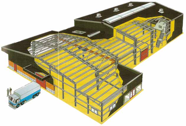
A complex of load-bearing structures that absorb loads from the weight of the building envelope (roof, wall panels, glazing), atmospheric (snow, wind) and crane loads is called the building frame. The frame can be steel, reinforced concrete or mixed - steel and reinforced concrete. The choice of frame material is determined by technical and economic calculations. Construction diagram steel frame a one-story industrial building is shown in the figure below. Based on the type of intra-shop transport, production buildings are divided into craneless, with overhead (figure below) and overhead (figure below) cranes. The choice of transport type is determined by the purpose of the building. The cranes move along crane beams that are mounted on columns or attached to crossbars. The main elements of the frame are transverse frames (figure below), consisting of columns, usually rigidly clamped in the foundation, and crossbars, rigidly or hingedly connected to the columns.
Crossbars can be solid (beams) or through (trusses). Solid crossbars have a smaller building height compared to through ones, are easier to manufacture and more convenient for transportation, but they consume more metal. Therefore, the main type of crossbar in frame industrial buildings is a truss truss. Where necessary, lanterns are provided for lighting and ventilation in buildings.
Structural diagram of the frame of an industrial building
1 - columns; 2 - trusses; 3 — monorail beams (for a suspended crane); 4—horizontal connections along the upper chords of the trusses; 5 - vertical connections;6 - connections along columns; 7 - purlins with strands (shown only on one span)
Vertical connections between the columns of the frame (see figure above) provide spatial rigidity and geometric immutability of the steel frame of the building in the longitudinal direction. They absorb forces from wind pressure on the ends of the building and longitudinal braking of cranes, and also increase stability from the plane of the frame. The simplest and most common design of connections is a cross (see figure above). Vertical connections between columns are arranged in the middle of the building, since these connections installed at the ends of the building prevent free thermal deformations of the longitudinal elements of the frame, which can lead to the occurrence of additional thermal stresses.
The distance between the axes of the columns (for stepped columns - between the axes of the crane part of the columns) is called the span of the building. According to the requirements for the unification of industrial buildings, the span is assigned in accordance with the enlarged module, a multiple of 6 m (rarely 3 m). Accepted spans are 18, 24, 30, 36 m and more. The distance between columns in the longitudinal direction, called the frame pitch, is also taken as a multiple of 6 m (usually 6 or 12 m). In multi-span buildings in the middle rows, the distance between columns can be increased to 18 or 24 m, but in this case the use of rafter trusses is necessary.
To support the wall fencing, glazing frames, gates and other elements, an end frame (see figure below) and, if necessary, a longitudinal half-timbering consisting of racks (columns), crossbars and spacers are installed. When self-supporting brick walls, as well as with enclosing structures made of prefabricated wall panels and a column spacing equal to the length of the panel, there is no longitudinal half-timbering. The half-timbered elements also absorb horizontal wind loads.
Transverse frames of the frame of an industrial building

1 - columns; 2 - crossbars (rafter trusses); 3 - overhead crane;4 — crane beams; 5 - hanging crane
