Industrial buildings types of coatings on a steel frame. One-story industrial enterprises. One-story frame buildings
Summary:
This section examines the most widely used frame structures and large panel industrial buildings. general information about them is given, detailed information about multi-storey industrial buildings is attached.
9.1. General information.
Industrial buildings (hereinafter P.z.), production buildings of industrial enterprises, buildings designed to accommodate industrial production and provide the necessary conditions for the labor of people and the operation of technological equipment.
The hotel has since burned down, but the residential island nestled in the middle of London's River Thames is still renowned for its arts community. After buying the site of the old hotel, it took seven years for architect Henry Harrison to get permission to build his new residence. However, the final result is impressive. The new building boasts a unique and modern design, but still matches the character of the island, blending in with the boats that still operate along the coast of the island.
Helsinki Convention Center Successfully Expands With Two-Piece Steel Pipes
It does exactly what you want with zero spring. It is just as strong and won't crack when installed in cold weather. The environmental impact of the building was also considered. The company delivers its products primarily on a turnkey basis, including design, manufacture and installation of products. Projects are implemented either as project projects or in accordance with client plans. In addition, some of its façade products also come without a service package.
As an independent type of building P. z. appeared in the era industrial revolution when there was a need for large rooms for machines and numerous workers. The first P. z. were rectangular in plan, with load-bearing brick or stone walls and wooden floors Purely utilitarian solutions prevailed: an extended array of unplastered walls was often segmented only by pilasters and was decorated with figured masonry belts. Sometimes in outdoor decoration P. z. decorative elements of various architectural styles were used.
Maximum speaker-free space at minimum cost. The exhibition and convention center, located in the Finnish capital of Helsinki, is the largest of its kind in the country, welcoming over a million visitors every year. The new hall, Exhibition Hall 7, was presented as a multi-purpose hall with maximum column-free space.
In addition, the frame had to be as economical as possible. Best results with bi-fold steel. The project called for a steel class that would allow for the construction of a 78-meter column-free zone. The steel frame consists of 17 separate 78m space trusses with a maximum height of 7m and a maximum width of 5m, each weighing between 65 and 80 tons. Each truss consisted of two 39-meter segments.
With the development of construction technology and the emergence of such new building materials, like metal and reinforced concrete, frame structures were developed, which made it possible to abandon traditional compositional schemes and create a rational layout of workshops in accordance with the requirements of production technology. Application since the end of the 18th century. in the construction of P. z. A frame made of cast-iron posts and beams made it possible to build less massive walls, increase the number of storeys and the size of light openings, which immediately had a noticeable effect on the appearance of the skylight. floors from metal trusses and their subsequent improvement made it possible to create large spans with rare supports that do not interfere with the installation of equipment
Sections with identical outer radii can be used. The use of clamshell steel in steel structures substantially reduces material costs while providing a financially attractive option. It also reduces the environmental impact of the use and production of materials.
The steel pipes were delivered cut directly from the factory to the customer, which allowed them to cut additional welding costs. They expect the self-cleaning surface to reduce maintenance costs and keep the building as good as new. When the architects planned the new De Grote Prins housing project, they were aiming for a lightweight façade concept that would make the buildings always new. This concept was considered integral to the identity of the object and to the value of the property.
In the 1930s-60s. in the construction of P. z. new structural systems are being widely introduced, which make it possible to block large spans without supports, new building and finishing materials are being used. In the conditions of the modern scientific and technological revolution with constant technical progress in the construction of the P. z. and the improvement of production technology, the number of enterprises that do not have a harmful impact on the environment is growing. As a result, a new type of building is being created - industrial and residential. They have their own large scale, spatial solution and silhouette, which differ from typical residential buildings. P. z. become important architectural accents in the composition of urban development.
At the same time, future operating costs and a reasonable solution for owners played an important role in the design requirements. Its combination of proven properties and new self-cleaning feature was cost effective and opened the door for architects to create an attractive façade.
The outer surface has self-cleaning properties, making it ideal for buildings that must meet high aesthetic requirements. At the heart of the self-cleaning properties, a special paint additive is added. The result is a paint finish that prevents dirt and impurities from sticking, and this is effectively washed off by rain. The paintwork is weather-resistant and wear-resistant.
The role of scientists in the formation and development of architectural science and practice is great, which has dramatically improved over last years quality and expressiveness industrial facilities. The works of scientists of the Republic of Uzbekistan, (Umarov A.A., Valiev R.M. and others) significantly influenced the development of architecture and urban planning with an industrial zone.
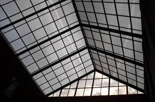
As follows from the works of scientists, the architectural image of P. z. to the greatest extent depends on how clearly the typological features of this type of structures are expressed in its appearance, its character traits: huge size and significant length of facades, large solid planes of blank walls and glazed surfaces corresponding to a single undivided internal space, repeatedly repeated ends of parallel spans, roofing elements (comb, sawtooth or curvilinear outlines), stairwells, etc., the presence technical devices(smoke and ventilation pipes, pipelines, open equipment, etc.). A great influence (especially with industrial methods of construction) is exerted on the appearance of P. z. artistic expression of the tectonic properties of the materials and structures used, as well as the texture and color of structural and finishing materials.
Schemes of frames of one-story industrial buildings
The optimal façade solution helps to reduce maintenance costs and improve the living environment. Lightweight, aesthetically pleasing and maintenance-free, the material keeps facades looking like new. Security is achieved through the use of proven, durable material from the market leader. And the Sofiemmet Hospital needed a new roof that could withstand the temperamental weather in Sweden, but be mild in the environment.
It was easy to work with and less sensitive to scratches. Since the eco-friendly coating was introduced, it has undergone rigorous testing in high security locations. The product has been subjected to strong sunlight, ocean salt spray and large temperature differences to confirm its good corrosion properties and color stability.
A significant role in the appearance of P. z. in the Republic of Uzbekistan, sun protection devices are playing - the so-called. sunscreens, visors, decorative grilles. Great importance to improve the aesthetic qualities of P. h. has a clear internal layout, rational proportions and divisions of individual rooms and a plastic solution to them structural elements, zoning of industrial premises with a systematic placement of the main technological equipment, intra-shop communications, aisles and driveways, color scheme of interiors, consistent implementation of a set of measures related to the requirements technical aesthetics. P. h . and structures have a huge (often negative) impact on natural and architectural landscapes; often industrial areas lose touch with the natural environment. Therefore, industrial architecture is faced with the task of preserving the natural landscape as much as possible and of harmoniously incorporating new landscape structures into the landscape.
Minimizes the ecological footprint. The colored surface has good mechanical strength and can withstand harsh climatic conditions. It has good formability and less sensitivity to cracking. Comes with corrosion and finish guarantee. Of all the industries that use steel, the construction industry consumes the most. However, buildings also offer the greatest potential for achieving significant emission reductions at the lowest cost. Solid design and design expertise is essential for complex construction projects especially since we always strive to work against the clock and the forces of nature.
On formation of types P. z. socio-economic conditions and scientific and technological progress in industrial production technology and construction equipment have a decisive influence. In the USSR and other socialist countries, the nature of the social system determined the emergence of socialist laws. new type, which embodied the achievements of social and scientific and technological progress. Development and improvement of architectural and construction solutions P. z. based on scientific research who determined the main directions of modern industrial construction, which provide for: ensuring the universality of production facilities, that is, the possibility of the most flexible use of production space when technological processes change; the unification of space-planning and design schemes for building construction, which makes it possible to make fullest use of the production base of the construction industry; maximum blocking (unification) of workshops and entire industries in enlarged buildings.
Different steels for one unique structure
Four planed trusses, each weighing 550 tons, support the roof. Its rafters are 531 feet long, 52 feet high and 49 feet wide. To ensure that the retractable roof structure worked as intended, the installation tolerances for the huge steel structures were extremely tight.
Public and industrial buildings
The high degree of structural assembly helped reduce construction risks and improve site safety. With one of the highest strength-to-weight ratios, steel is lighter than any other material. This reduces the foundation requirements for any steel building, from skyscrapers to aircraft hangars or public arenas. And in particular, high-strength steels are becoming increasingly important for industries that want to produce products that are both lightweight, strong and energy efficient.
9.2. reinforced mesh columns.
Universality P. z. is achieved by using enlarged grids (spans and steps) of columns and a single height of rooms within each building, as well as using collapsible partitions to accommodate the main equipment and whatnots, providing the possibility of modernizing technological processes with a minimum amount of work on the reconstruction of the building. Unification of space-planning and design schemes allows you to significantly reduce the number of standard sizes of products and structures, create the necessary conditions for their mass factory production and widespread introduction into construction practice. In the USSR, an intersectoral unification of the main construction parameters of the railway system has been carried out: grids of columns, floor heights, dimensions for linking structural elements to modular center axes, and so on. The dimensions of the grids of the columns of one-story P. z. taken as multiples of 6 m, the size of the spans of multi-storey P. z. -3 m, column pitch - 6 m. Height of floors P. z. multiple of 0.6 m. Blocking P. z . (cm. Blocked production building) - one of the most effective means decrease estimated cost construction P. z. The greatest reduction in capital costs due to blocking (compared to separately constructed workshops) is achieved in cases where it is not required to isolate workshops from each other with main walls, equalize the heights of adjacent premises in order to unify structures, arrange additional intra-shop passages or increase the area of zones served by heavy duty cranes.
And because less steel is required, less needs to be transported. All in all, the use of special steels has reduced the weight of the trusses in the Arenas of Friends by almost 600 tons - about 70% compared to conventional steel - worth 2 million euros. These cost savings were mainly due to fewer welds and lower heating temperatures when welding high-strength steels. Sometimes words like sustainability, material efficiency, and energy efficiency sound a bit vague.
Transverse frames of the frame of the industrial building
Here are some numbers that determine the effectiveness of the project. The challenging Friends of the Arena project has shown that high-strength steels in super systems are a viable solution that helps reduce overall project costs, simplifies the processing of structural elements, and promotes sustainable construction.
P. z. they are distinguished according to the following main features: by number of storeys (the main classification feature) - into one-story, two-story, multi-story; for handling equipment - for cranes equipped with overhead (electric) and overhead (electric or manual) cranes, and craneless; in appearance lighting- for buildings with natural lighting (side and top), with permanent working artificial lighting (windowless and lampless) and buildings with combined lighting (combining natural lighting with artificial lighting); for air exchange systems - for buildings with a common natural ventilation(aeration), with mechanical ventilation and with air conditioning; according to the temperature regime of industrial premises - into heated and unheated. According to the capital of P. z. are divided into 4 classes depending on the purpose of the buildings and their national economic significance.
Main frame design process
It also plays an important role in restraining primary steel members from buckling out of plane. Location of the portal frame, showing the main structural components and their connections. Software, designed specifically for portal frame analysis and design, will generally be used for efficient design.
The process of designing the main frame and additional components. Set a clear range and height based on customer requirements. The geometry used in the structural frame analysis should be slightly conservative to allow for any potential changes in penis size, while still maintaining the specified height from the finished floor level to the bottom of the protrusions, which cannot be changed.
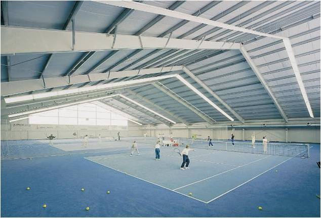
One-story P. z. - the most common type of industrial buildings. Their share in the total volume of modern industrial construction is 75-80%. One-story P. z. Usually they are used to locate industries with heavy technological and material handling equipment or those involved in the manufacture of bulky bulky products, as well as industries whose operation is accompanied by the release of excess heat, smoke, dust, gases, and so on. create favorable conditions for the rational organization of the technological process and modernization of equipment, they allow the foundations of heavy machines and units with large dynamic loads to be placed directly on the ground, provide the possibility of uniform lighting and natural ventilation of the premises through lighting and aeration devices in the coating.
Set actions based on location, site elevation, and local topography. Permanent actions can be evaluated based on the chosen type of cladding. Some typical weights roofing materials shown in the table below. Equivalent horizontal forces are not strictly actions, but forces applied to the frame in combination with other actions model the effect of frame imperfections.
Step 4: Selecting the Starting Element
Global disadvantages for frames and fastening systems. local disadvantages for individual members. During initial construction, rafters are usually selected according to their lateral resistance to bending and axial force. For more late stages design, it is necessary to check the resistance to buckling, and the restrictions are reasonable.
9.3. Single storey frame buildings.
Reinforced concrete frames of one-story buildings (industrial, agricultural, etc.) consist of columns and rafters, trusses and arches, and, if necessary, of crane and strapping beams, etc. All the main loads in such buildings are transferred to the frame, and the walls are self-supporting . In some cases, constructive schemes of buildings with an incomplete frame are used, in which, instead of the extreme rows of columns, load-bearing walls (usually with pilasters) are provided. Reinforced concrete frames of buildings should be designed from prefabricated standard elements with spans of 6, 12, 18, 24, 30, 36 m, column spacing of 6 and 12 m. In buildings with overhead cranes, rectangular and two-branch columns with consoles for crane beams are used.
The initial selection of a column section is likely to be based on its buckling resistance rather than its cross-sectional resistance. Compared with roof structure, as a rule, there is less freedom in the arrangement of the rails in order to contain buckling, since the positions railways may be dictated by doors or windows at a height.
Out-of-plane stability tests differ for parts of elements on and near plastic hinges, and parts of elements that are elastic. In all cases, checks are made between constraints. Expression 62 should be used to test the elastic parts of elements out of plane between the holding devices.
In craneless buildings, rectangular columns without consoles are used. Reinforced concrete columns are rigidly embedded in glass-type foundations. On top of the columns rest the crossbars of the frame, which are a rafter beam, truss or arch.
For wall filling of the building frame, the most industrial types are used. wall structures- reinforced concrete wall panels with a length equal to the pitch of the columns, i.e. 6 and 12m. in heated buildings, insulated panels are used, which can be two-layer (reinforced concrete ribbed panel filled with lightweight porous concrete) or single-layer made of lightweight reinforced concrete, reinforced concrete, etc. The panels are attached to the columns with bolts or welding of embedded parts.
Types of one-story frame buildings
It is important for the designer to carefully study the nature and location of all constraints in order to cover all combinations of loads. The flange in compression that requires containment will differ depending on the load. The illustration shows how the inner flange of the rafter is restrained by the purlin connection. Refer to section 8 for more details on restrictor design.
Step 7: Joint Design and Detailing
The resistance of the foundation to horizontal forces can be achieved in several ways. Connection across the entire width of a frame connecting both columns at the bottom or inside the floor slab.
- Passive earth pressure on the foundation side.
- The tie is inserted into the floor slab connected to the base of the column.
A feasibility study shows that one-story buildings with precast concrete frames are more economical than buildings with steel frames. So, with a grid of columns of 624 m, the consumption of steel per 1 m 2 of the area of \u200b\u200bthe building is reduced by 2.5 times only due to the replacement of steel trusses with prestressed reinforced concrete ones.
One-story industrial buildings.
Types of one-story frame buildings
Industrial buildings are mainly designed and erected as one-story buildings (about 70%). Such buildings house production facilities with heavy and bulky equipment that cannot be placed on floors. multi-storey buildings, as they are too powerful and uneconomical. The conditions for the placement and operation of the equipment, as well as the need to change the technological process in the future, require a large grid of columns and a high building height. One-story buildings are in many cases equipped with overhead overhead cranes of significant lifting capacity, which create large forces in the bearing elements of the building. One-story buildings are widespread in the metallurgical, engineering, and other industries.
There are the following types of one-story industrial buildings: single-span and multi-span; buildings without overhead cranes (50%), with overhead (15%) and overhead cranes (35%); buildings with lanterns and without lanterns; buildings with pitched and slightly sloping roofs. It is recommended to design one-story industrial buildings rectangular in plan, with the same spans, without height differences in order to avoid snow bags. The question of choosing the material of the supporting frame should be decided on the basis of a technical and economic analysis. The main material for one-story buildings is precast concrete. Buildings are erected from it for 85% of production areas, while from metal - only for 12%, and from other materials - for 3%. Steel supporting structures are recommended for large spans and building heights in buildings with heavy crane equipment, if it is necessary to install overhead cranes in two tiers, and in construction in remote areas.
Building layout. Frame buildings are designed with the obligatory observance of modular dimensions, adopted on the basis of the Unified Modular System. For industrial buildings, a span of up to 12 m is taken as a multiple of 3.0 m, and for a larger span - a multiple of 6.0 m. The height of the premises is set as a multiple of 0.6m for a height of up to 6m and a multiple of 1.2m for a height of more than 6m. The pitch of the columns is taken as 6 and 12m. Not only space-planning parameters are unified: span, column spacing, room height, but also their mutual combinations, called unified overall schemes.
The main load-bearing elements of a one-story frame building are transverse frames, which perceive loads from the mass of the coating, snow, cranes, wind pressure on the longitudinal walls and ensure the rigidity of the building in the transverse direction. The transverse frame of the building consists of columns embedded in the foundations or block part of the building, and a roofing crossbar (beam or truss) resting on the columns.
Columns are usually rigidly connected to foundations, and crossbars with uprights are rigidly or hinged. For prefabricated structures, swivel joints are more often used. In this case, the load applied to one of the elements does not cause bending moments in the other. This makes it possible to independently type the crossbar and columns, simplifies the design of the joint, and allows mass prefabrication of elements. As a result, one-story frame designs with hinged joints are more economical, despite the fact that the forces in them are greater than with a rigid connection of the elements. Structurally, the connection of the crossbar with the column is carried out using anchor bolts and field welding of the base sheet of the crossbar with the embedded part in the column.
Breakdown of the building into temperature blocks. Due to the large size of industrial buildings in plan and the continuity of the coating, which is a single rigid slab, changes in outdoor temperature cause noticeable deformations (lengthening and shortening) of transverse and longitudinal crossbars, crane beams, etc. Shrinkage of concrete leads to similar deformations, causing shortening of elements . These deformations cause the occurrence of significant additional forces in the columns, which can cause the formation of excessive cracks and the destruction of some of the elements. To reduce this kind of effort in the structures, temperature-shrinkage joints are provided, arranged on paired columns with the seam brought to the top of the foundation.
If the distance between the seams does not exceed certain values, and the crossbars of the coating belong to the 3rd category in terms of crack resistance, then the calculation for temperature effects may not be carried out. In this case, the maximum allowable distance l td between the seams is 72 m in heated one-story industrial buildings made of precast concrete, and 48 m in unheated buildings. In some cases, it turns out to be appropriate to calculate the frame for temperature effects and increase l td. This saves money by reducing the number of crossbars. Temperature t and shrinkage sh deformations within the block are calculated by the formulas:
T = b l td t 0 ; sh = sh l td ,
Where b is the coefficient of linear thermal deformation of concrete, equal to 1. 10 -5 1/deg; sh - coefficient of linear shrinkage of concrete, equal to
15 . 10 -5; t 0 is the maximum calculated temperature difference.
The forces in the structures caused by the specified deformations are determined by the methods of structural mechanics. In cases where a building is being erected on a site with heterogeneous soils, as well as when its parts have different heights and their uneven vertical displacement is possible, sedimentary joints are arranged. They cut the building, including the foundations, to provide parts of the building with an independent draft. Sedimentary seams are usually combined with temperature-shrinkage seams.
Ensuring the spatial rigidity of the frame. The spatial rigidity of a building or structure is its ability to resist horizontal loads. Ensuring spatial rigidity is important, since excessive movements of the frame can lead to disruption of the normal operation of the building (cranes, etc.). The spatial rigidity of the frame of a one-story industrial building in the transverse direction is provided by the calculation and design of the transverse frame. This is explained by the fact that in this case special connections cannot be established, since they would interfere with the technological process. Therefore, the main factors that provide transverse spatial rigidity are pinching of columns in foundations and sufficient bending rigidity of columns. The spatial rigidity of the building in the longitudinal direction and the perception of longitudinal horizontal loads (wind pressure on the end of the building, the longitudinal force of the crane) are provided by the longitudinal frames of the building. They include columns transverse frames, foundations, floor slabs, crane beams and vertical ties.
Vertical connections are established along the elements of the coating and along the columns. According to the elements of the coating, the connections are placed in the extreme spans of the temperature block along the longitudinal axes at the level of the supporting parts load-bearing structures coatings. With a pitched roof and a height of the supporting part of the crossbar up to 900 mm, you can not put connections. Vertical connections along the columns are installed in the middle of the temperature block. In craneless buildings with a height from the floor level to the bottom of the supporting structures up to 7.2 m inclusive, vertical connections along the columns are not installed.
Reinforced concrete building beams and floor slabs
Reinforced concrete building beams are used to cover spans of 6.9.12 m. With spans of 24m or more, they are inferior to trusses in technical terms - economic indicators and are generally not used. Beams with spans of 6 and 9 m are intended mainly for covering. Beams with a span of 18m are used as transverse crossbars, along which 3x6 or 3x12m slabs are laid. Depending on the profile of the roof, the beams are gable, single-pitched, with parallel shelves, with a broken or curvilinear outline of the upper shelf. Gable beams have an upper flange slope of 1:12 for pitched roofs, 1:30 for slightly sloping roofs. Due to their cost-effectiveness, they are most often used for covering spans of 18m. Certain difficulties in their manufacture are associated with the arrangement of frames of variable height. If it is necessary to skip communications at the level of coverage (air ducts, etc.), double-pitched lattice beams with a span of 12 and 18 m are used. One-act beams are usually used for roofing with a one-sided slope, for example, in extensions.
Beams with parallel flanges are the easiest to manufacture, have reinforcing cages of constant height and are used as longitudinal crossbars for horizontal roofs. .However, in terms of concrete and reinforcement consumption, they are inferior to gable ones. Beams with a broken and curvilinear upper girdle, despite the cost-effectiveness, have not found wide application due to the complexity of their manufacture. The height of the section of the beams in the middle of the span (1/10 ... 1/12) l.
In order to save concrete, the cross section of the beams is crushed with a T-shaped
(at l = 6; 9m) and I-beam (l = 12; 18m). The width of the upper flange of the beams from the condition of the plumage of the coating slabs and ensuring stability during transportation and installation is taken equal to 1/50..1/60, which is usually 20..40 cm. The thickness of the vertical wall in the middle part of the span (6 ... 8 cm) is assigned based on the conditions for manufacturing the beam (in a vertical position) and the placement of transverse reinforcement (one or two frames).
Cover beams are made of heavy concrete of classes B25 ... B50 and concrete on porous aggregates of classes B25 ... B40. Basically, prestressed structures are used, reinforced with high-strength rods, a single high-strength wire or bundles of it, seven-wire ropes are also used. Beams are manufactured at factories of building materials and structures with reinforcement tensioned on stops.
Typical beams with a solid I-beam cross section and lattice beams are designed with several options for reinforcement with longitudinal prestressing reinforcement of classes A - IV, A-V, A-VI, Vr-II and K-7. The beams are designed for uniformly distributed loads from their own weight, the weight of the roof and snow, as well as concentrated forces from the weight of the lantern and overhead transport, if any, in the building, while taking into account the most unfavorable combination of loads.
Reinforced concrete roof trusses
Reinforced concrete roof trusses are used as crossbars for covering industrial and public buildings with spans of 18.24.30 m in steps of 6 and 12 m. With large spans, reinforced concrete trusses turn out to be heavy, inconvenient during transportation, laborious in installation and can only be used with special justification. The outlines of building trusses depend on the roof profile and the overall layout of the coating. In terms of material consumption, segment trusses with a curvilinear or broken upper chord are the most rational, since their outline largely coincides with the diagram of moments from an external load. The lattice of segmental trusses can be triangular and without diagonal. Bezraskosnye trusses are less economical in terms of material consumption, since significant bending moments occur in the chords and posts of such trusses, and in the triangular lattice of reinforced concrete trusses, the rods work in compression or tension. However, the complexity and cost of manufacturing without diagonal trusses is lower than that of trusses with a triangular lattice. When erecting one-story industrial buildings, gable polygonal trusses are often used; for flat roofs, trusses with parallel belts are used.
The dimensions of the panels are usually assigned equal to 3m. The height of trusses in the middle of the span, depending on the type of truss, is in the redistribution () . With spans up to 18…24 m, the trusses are usually made in one piece, with spans over 24 m, they are made of separate elements connected using field joints in the middle of the span. Tensile elements of trusses (finding costs and lower chords) are usually made prestressed. For prestressing reinforcement, hot-rolled reinforcing bars of a periodic profile of classes
A-IV, A-V, A t -IV, reinforcing seven-wire strands of class K-7, ropes and bundles from high-strength weeding. The design of a precast concrete truss with a span of 24m is shown. The anchoring zone is prestressed with rod indirect reinforcement using meshes. The upper chord and lattice rods are reinforced with welded frames.
Reinforced concrete truss arches
Arches are called systems consisting of curvilinear elements, the horizontal displacement of the supports of which is limited. This leads to the appearance of a spacer, which ensures the operation of the arch mainly in compression. In one-story industrial buildings, arches are used in covering medium and large spans. There are examples of the use of arched structures in hangars, sports facilities, bridges, where spans exceed 100m.
Depending on the static scheme of operation, the arches are non-articulated, two-articulated and three-articulated. They can be erected with or without puffs, in the latter case, special foundation designs should be provided for the perception of thrust. The simplest in manufacturing and erection are hingeless arches, however, since these are statically indeterminate structures, additional forces may appear in them due to settlement of supports, temperature deformations, creep and shrinkage of concrete. The most economical are double-hinged arches with puffs that perceive thrust. The lifting boom of such arches is taken within the ratio of the height of the cross section to the span should be h / L = 1/30 ... 1/50. Three-hinged arches are used less often, since in this case additional work is required on the arrangement of hinges and the construction of heavy foundations for the perception of thrust.
The shape of the axis of the arch is most often taken as circular, less often parabolic. The optimal outline of the arch axis is such when it coincides with the diagram of moments. The cross section of the arches is accepted as rectangular, I-beam, box-shaped, lattice and folded. Longitudinal reinforcement in the section is placed structurally, reinforced concrete puffs must be prestressed, they are designed similarly to the lower chords of trusses. Support nodes arches are shown. In the areas of anchoring of prestressing reinforcement, indirect reinforcement should be provided welded meshes. To eliminate the sagging of the puffs, reinforced concrete suspensions are arranged after 5 ... 6 m from one another.
Reinforced concrete frames
Reinforced concrete frames are flat rod systems, in which geometric immutability is ensured by rigid connections at the nodes. Depending on the number of spans, frames are single-span, multi-story. Crossbars of frames of one-storey buildings are made, their connection with frame columns is, as a rule, rigid. Racks of frames can have a rigid or articulated connection with the foundations. Application prestressing in crossbars allows (frame solutions with spans up to 60m are known).
Schemes of single-span three-hinged frames with a broken crossbar, which may or may not have unloading consoles, are widely used. Frames are spacer structures, the work of which resembles the work of arches. In terms of material consumption, frames are somewhat less economical than arched structures, but in terms of simplicity and labor costs for manufacturing and installation, they are more preferable. According to the manufacturing method, the frames can be monolithic and prefabricated. Monolithic frames are used relatively rarely due to the complexity of the production of reinforcing and concrete work. The nodes for connecting the elements of monolithic frames with foundations, in the eaves and ridge, as a rule, are made rigid. Precast concrete frames are used much more often.
Structural scheme multi-storey buildings
Multi-storey buildings according to the constructive scheme are divided into frame, panel, three-dimensional - block and combined. One or another type is chosen based on the functional purpose of the building, the presence of an industrial base, number of storeys, economy, construction conditions (permafrost, seismic). In industrial construction, multi-storey frame buildings without special vertical diaphragms are most convenient, since they can limit the free placement of process equipment and industrial communications. These buildings usually have a reinforced concrete frame and self-supporting or curtain walls. The main elements of the frame, as in a one-story building, are columns, crossbars, floor slabs and coatings. Sometimes buildings are erected with an incomplete frame and bearing walls. Multi-storey civil buildings are represented by all three structural systems (frame, frameless, mixed), but more often they adopt a frameless system (panel buildings) or a combined system.
Frame buildings. These buildings are used to obtain large premises. These are primarily industrial, administrative and public buildings. In frame buildings, all loads are transferred to the frame, which ensures the strength and stability of the building under all types of impacts. The main elements of frame buildings are reinforced concrete columns, crossbars, vertical stiffeners.
panel buildings. IN residential buildings, hotels, hostels need frequent location internal walls and soundproofing. For the necessary sound insulation, the internal walls must have a density of at least 0.3 t/m2, which corresponds to a concrete thickness of 16 cm. Such walls, having sufficient strength, do not need a frame. They connect and form a spatial system capable of absorbing horizontal and vertical loads. Buildings of this design are called panel buildings. In the latter case, retail premises can be arranged in extensions to the main volume of the building, using the volume of the lower floors of the main building for utility rooms.
Volumetric - block buildings. A further improvement of panel structures are volumetric blocks manufactured for a room or apartment. The volumetric - block diagram is distinguished by the greatest factory readiness. Labor costs for the manufacture of blocks are 75 ... 80% of the total labor costs. Apply "block - glass", "block - cap", "block - glass lying." Blocks are made monolithic or from flat panels by welding embedded parts. Then the block enters a special conveyor, on which finishing and sanitary works are carried out. The mass of the block is up to 10 tons. The blocks rest on each other in the corners or along the joining lines of the walls. In the first case, the number of storeys of block buildings is usually limited to five floors. The disadvantage of this type of buildings is the limited planning solutions, a small variance in the placement of blocks in the building plan.
Combined buildings. In multi-storey buildings erected in large cities on the main highways, it is advisable for sanitary and hygienic conditions (noise, dust, gas pollution) to locate living quarters starting from a height of two to three floors, using the first floor for shops, driveways, garages. In this case, the panel structure of the building is located on a monolithic or prefabricated reinforced concrete frame. This design is called combined. The development of the structural part of the project of a multi-storey frame building consists in the choice of the structural scheme of the frame and its layout, the calculation of the building, its individual elements and interface and design nodes.
The choice of the frame scheme and its layout is carried out taking into account the purpose and space-planning solution of the building, technological solutions, production base and technical and economic analysis. It includes the choice of the way to ensure the spatial rigidity of the building, the grid of columns, the direction of the crossbars, the scheme of dividing the load-bearing system into prefabricated elements, etc. The grid of columns is usually set by architects, taking into account the requirements of technologists and the Single Modular System. The direction of the crossbars can be longitudinal and transverse. The most important thing when choosing a frame scheme for a multi-storey building is the question of the perception of horizontal loads, i.e. on ensuring spatial rigidity. It can be solved by appropriate design of the frame nodes or by installing special vertical stiffeners. On this basis, the carrier systems of the frame are divided into frame, frame-bonded and bonded.
frame system. In the frame system of the frame, the supporting functions are performed by columns and crossbars. The crossbars are rigidly connected to the columns, as a result of which a spatial system is formed, consisting of flat frames. The frames perceive all the vertical and horizontal loads acting on the building and transfer them to the foundations. With an increase in the number of storeys of the building, the bending moments from the wind load in the columns and crossbars of the lower floors increase, which requires an increase in the cross section of the crossbars. These systems are used in buildings with no more than 8 floors if it is unacceptable to install diaphragms in rooms, if there are openings in the ceilings of buildings, etc.
Frame - connection system. In ranks of more than 8 floors, horizontal loads are perceived by frames with rigid nodes and vertical stiffeners, and vertical loads - by frames and partially - by stiffeners. As such elements, reinforced concrete walls are usually used - diaphragms, as well as metal ties and other designs. Diaphragms can be with openings and without openings, and according to the configuration in plan - flat, angular, I-beam, etc. It should be strived for the diaphragms to be as evenly distributed as possible along the plan of the building and linked to the frame, connected into a spatial system by ceilings, which, in addition to the main work on vertical loads and redistribute them between frames and diaphragms.
Communication system. Vertical load is perceived by frames and partially by diaphragms. The junction of the crossbar with the column is solved in such a way that it can perceive a pre-task small reference moment necessary to ensure the spatial rigidity of the building during its installation. The constancy of the moments allows you to completely unify the nodal connections and, accordingly, the crossbars and columns of the frame. IN Lately purely hinged joints of crossbars with columns have been developed and are being implemented, allowing to further reduce metal consumption. Spatial rigidity during the installation of the building in this case is provided by temporary connections.
Communication system received most widespread in multi-storey residential and public buildings from precast concrete. Frame - tie system is recommended for use in construction in seismic areas.
In buildings with a height of more than 20 floors, in many cases, the vertical structures of elevator shafts, ventilation chambers, and staircases are combined into stiffening cores. Such a solution is convenient in planning and technologically advanced. The walls of the stiffening cores are made of monolithic reinforced concrete. The core perceives all the horizontal loads acting on the building and that part of the vertical ones that falls on the core itself; the remaining vertical loads are taken by the frame. In buildings with a height of more than 50 floors, the stiffening cores are not able to absorb the wind load. In this case, the outer columns of the building with the help of horizontal diaphragms (grillages) are combined with the stiffening core and work together with it.
Reinforced concrete structures of multi-storey buildings
public and industrial buildings
For multi-storey public and industrial buildings, depending on the loads and spans, a variety of frames with different column spacings are used. Sometimes large-span (hall) and small rooms are combined in one building, i.e. frames with a mixed grid of columns are used. In public buildings, bonded frames and large-span are used, in industrial buildings - frame frames and large-span. The vertical load-bearing elements of such buildings include columns, crossbars, diaphragms, stiffening cores. The height of industrial buildings is assigned according to the conditions of the technological process and is usually understood to be equal to 3 ... 7 floors. It is planned to increase the number of storeys up to 8…10 and more. In accordance with the requirements of unification, the floor height is a multiple of 1.2 m. The width of the building is usually 12…60m. The most common grids of columns are 6x6, 9x6 and 12x6m. The dimensions of the grid of columns are assigned taking into account temporary loads (10 ... 30 kN / m 2).
The spatial frame of industrial buildings is solved by a mixed system. Strength and stability in the direction of a frame with rigid nodes in longitudinal - vertical steel ties along columns arranged in each longitudinal row or sparsely through a row of columns or more. If in the rest, then to ensure the stability of the frame in the longitudinal direction, it is possible to install “frame abutments” in one or more spans. Multi-story prefabricated frames are divided into separate elements, which are connected by rigid joints. The most widespread are prefabricated frames with joints of crossbars and columns, performed on consoles.
An industrial solution is the use of continuous prefabricated reinforced concrete columns and ceilings from “two T” slabs. Columns join through 1,2,3 and even 4 floors; the latter is more economical, since the number of joints is reduced. In most cases, the joint of the columns is arranged with flat ends of the columns and is carried out by bath welding of the outlets of the longitudinal working reinforcement, followed by monolithic. It is possible to connect fittings and joints using epoxy resins and. etc. The section of the columns is 400x400 and 600x400mm, concrete of classes B20 ... B50 is used. Prestressed ribbed panels 1500mm wide are usually recommended for intermediate floors. Panels laid along the axes of the columns serve as spacers and transfer longitudinal loads to the ties, and also provide longitudinal stability of the frames during installation.
Crossbars are of tee and rectangular section, in the first case, the panels rest on the shelves, in the second - on top of the crossbar. Crossbars for spans of 6 m are made of concrete of classes B15 ... B25, for spans of 9 m - from tone classes B30 ... B40. Crossbars for spans of 6 m are made with non-stressed and prestressed reinforcement, and for spans of 9 ... 12 m - only with prestressed reinforcement. If, according to the conditions of the technological process, a large grid of columns is required, then the building is designed with intercompany floors. In this case, the braced trusses are rigidly connected to the columns, and they work as crossbars of multi-storey frames. Intercompany space is used for production facilities.
Multi-storey industrial buildings with relatively small payloads (up to 12.5 kN/m 2 ) can be solved using a bracing system in both directions using lightweight frame structures. The columns in this case have a section of 400x400mm. Crossbars of the tee section are connected to the columns using a hidden joint. Covered slabs can be flat with a section height of 220mm or ribbed with h=300mm. The spatial rigidity of such buildings is ensured by the installation of vertical elements on all floors - diaphragms made of reinforced concrete panels, steel ties or single-span multi-storey frames.
When designing, even taking into account only the main features of the deformation of multi-storey buildings, computers are used to calculate them. For a number of specific structures in the form of impacts, it is possible to apply even more simplified schemes, for example, to divide the spatial system of a building into parts, each of which is calculated independently for the loads applied to it as a flat system. In these cases, engineering calculation methods and auxiliary tables well known to designers can be used for calculation. This approach is necessary for a preliminary approximate assessment of the forces occurring in the elements of the building, and in many cases it provides sufficient accuracy.
Reinforced concrete structures of multi-storey buildings civil buildings
Frame buildings. Multi-story civil frame buildings are widely used to accommodate trade enterprises, as administrative, residential, etc. Usually they are solved by frame-and-frame or connection systems, the latter is used more often. The vertical load-bearing elements of such buildings include columns, diaphragms and stiffening cores. The columns of buildings of mass construction with a height of up to 16 floors have a unified section of 400x400mm. An increase in their bearing capacity in the lower floors is achieved by increasing the class of concrete (up to B60) and the percentage of reinforcement with flexible reinforcement (up to = 15%). At the same time, longitudinal reinforcement is installed from steel of class A - III. Rigid reinforcement can be used for columns of higher-rise buildings, but its use in columns leads to a large consumption of steel.
It is possible to increase the bearing capacity of columns and maintain their unified section by transverse reinforcement with often located welded reinforcement meshes in combination with longitudinal ordinary and especially high-strength reinforcement. In this case, the limiting longitudinal deformations of concrete during compression increase by more than 2 times and the stresses in the compressed high-strength reinforcement reach the conditional yield strength. Along with this, proposals appeared to strengthen the columns of the lower floors, loaded with longitudinal forces with small eccentricities, with cores made of high-strength flexible reinforcement.
Diaphragms, which perceive mainly horizontal loads, are usually formed from reinforced concrete panels 14 ... 18 cm thick, located between the columns and connected to them by means of shear forces. Diaphragm panels can be flat or double cantilevered. Two consoles are placed in planes parallel to the frames of the frame, combining them with crossbars. The panels are reinforced with contour and intermediate frames made of rods with a diameter of 12 ... 16 mm or wire meshes with a diameter of 5 ... 6 mm with a step of 200 mm, located at both faces. Connections between panels and columns are carried out by welding embedded parts: vertical seams are filled with cement-sand mortar, horizontal seams are filled with concrete on fine gravel. Horizontal joints of diaphragms can be capped and flat. Practice shows that with such a connection, the diaphragms work like solid monolithic pillars.
The number and arrangement of diaphragms in the building plan must provide the necessary strength and spatial rigidity of the building in both directions, prevent its torsion in the plan, and not create large thermal forces or uneven deformations of the vertical elements. One should strive to reduce the total number of diaphragms by increasing their size. At high horizontal loads in diaphragms, usually operating in compression, tensile forces may occur in some sections. In this case, the diaphragms can be designed prestressed.
Stiffening cores are made monolithic and prefabricated. The cross section of the stiffening cores can be box-shaped, I-beam, etc. Monolithic stiffening cores are made in a sliding or adjustable formwork, while leaving holes for doorways and installation of crossbars. Wall thickness 20…40cm. Prefabricated cores are assembled from individual wall panels like flat diaphragms. In buildings with a significant length or complex shape in plan, several stiffening cores can be arranged. Slabs and crossbars make up prefabricated ceilings. The crossbars are designed with a T-section with a shelf in the lower zone, on which the floor slabs rest; this solution allows to reduce the construction height of the floor, however, in this case, it is necessary to exclude the possibility of the shelf breaking off at the place of its junction with the rib by increasing its height or reinforcing. Limitations of the support moment by a given value (55 kN. m) are achieved using a special metal lining on the top of the crossbar - a “fish”, welded to the crossbar and column. The "fish" has a narrowed section, the cross section of which corresponds to the tensile force at a given reference moment. An increase in load causes plastic deformations in the narrowed part of the lining, which ensures the rotation of the cross section of the crossbar without increasing the support moment. The junction of the tie frame can also be solved by articulated ones. Its design differs from that considered by the absence of a “fish”. In frame - tie systems, where nodes perceive bending moments from operational loads, the joint is fundamentally performed in the same way as in frame systems.
panel buildings. These buildings are typical mainly for residential construction. The width of buildings from the conditions of the premises is assigned 12 ... 16m. Panel houses mass construction are resolved in one of the following options; 1) with longitudinal and transverse bearing walls; 2) only with longitudinal bearing; and 3) only with transverse bearing walls. The design scheme with transverse load-bearing walls is more advantageous, since the floor panels in this case are based on internal transverse walls(partitions), which allows you to extremely enlarge and lighten the outer wall panels. The latter, not perceiving the load from the floors and are made of lightweight efficient materials. The main structures of panel buildings are internal and external wall panels and floor panels.
Internal load-bearing wall panels are usually designed as single-layer heavy-duty concrete of at least B15 class. The thickness of the panels is determined by the requirements of strength, sound insulation and fire resistance. External load-bearing walls are made in the form of single-layer panels 240 ... 350 mm thick from cellular concrete. External load-bearing panels are designed mainly with two or three layers. The reinforcement is installed only in layers of heavy concrete and is made in the form of a spatial reinforcement block. The design is only the fittings of the jumpers. Floor panels are made in the form of multi-hollow or solid slabs. For spans up to 4.8 m, the slabs are made without prestressing, for large spans they are prestressed. In a building with longitudinal and transverse load-bearing walls (the first option), the panels work like plates supported on three or four sides, in other cases - on two.
Connections of wall and floor panels must ensure the joint work of the elements in the building and the perception of compressive, tensile and shear forces. Vertical joints between the panels are carried out using concrete key joints and welding of embedded parts. Horizontal joints according to the method of transferring compressive forces are divided into platform, contact and combined. Interfacing of internal walls with ceilings is usually performed with platform joints, external - with platform and combined.
In recent years, a constructive solution has been developed, called the "hidden frame", combining the advantages of frame and panel type buildings. Bearing vertical structures are panels reinforced with side steel elements. Hidden frame structures are more economical than conventional frame structures due to the good collaboration of panels with side elements and allow you to increase the number of storeys of a building to 50 or more.
Multi-storey buildings.
9.4.1. Civil buildings.
Currently, the main types of buildings are frame-panel and large-panel (frameless), assembled from large-sized prefabricated reinforced concrete products factory made.
Frame-panel buildings are designed with a full or incomplete frame. With a full frame, the ribbed floor panels rest at the corners on the columns. The columns and ribs of the floors form the spatial frame of the building. Wall panels and internal partitions are self-supporting and are attached to the frame posts. With an incomplete (internal) frame, there are no extreme columns, and the panels of the outer walls are load-bearing. Floor panels are supported by load-bearing outer walls and inner columns of the frame.
Widespread, especially in housing construction, large-panel (frameless) buildings; due to the absence of a frame and an increase in the degree of prefabrication of the elements, the labor intensity of installation and the cost of such buildings are reduced.
Multi-storey frame buildings house light industry enterprises (instrument making, chemical, textile, etc.), refrigerators, warehouses, and garages. As well as hotels, medical institutions, etc. The height of industrial buildings, based on operating conditions and economic feasibility, is prescribed within seven floors (up to 40m), and civil buildings - up to 12 floors; high-rise buildings have 20 floors or more. The width of multi-storey industrial buildings in order to unify structural schemes is assumed to be 18, 24, 36 m or more, the distance between the transverse alignment axes (column spacing) is 6 m (sometimes more - up to 18 m), the height of the floors is a multiple of the module 0.6 m. The width of civil buildings usually does not exceed 14m. Multi-story frame buildings are designed with a full frame, where the walls are self-supporting or hinged, and with an incomplete frame, when the extreme rows of frame racks are replaced with load-bearing walls. Industrial buildings are designed mainly with a full frame.
Multi-story frame buildings are a system of transverse frames connected in the longitudinal direction by interfloor floors that are rigid in their plane. Overlappings can be beamed or beamless; in the latter case, the crossbar of the frame is reinforced concrete slab, rigidly connected with the capitals of the columns. Vertical loads in frame buildings are in all cases transferred to transverse frames. Depending on how horizontal loads are perceived, frame buildings of frame and frame-braced structural systems are distinguished.
In frame system buildings, horizontal loads (wind) are completely transferred through walls and ceilings to transverse frames, which must be designed to absorb such loads. In the buildings of the frame-and-braced system, horizontal loads are transferred through the outer walls to the intermediate floors, which, acting as horizontal diaphragms, transfer pressure to the vertical braced diaphragms. Such diaphragms can be transverse and end walls, blocks of stairwells, etc. Vertical bonded diaphragms work on horizontal loads as cantilevers, clamped in the foundation. With insufficiently rigid vertical connection diaphragms, part of the horizontal loads is transferred to the transverse frames.
9.4.2 Industrial buildings.
Multi-storey P. z. are built mainly for industries requiring the organization of a vertical (gravity-flowing) technological process, as well as for a number of industries equipped with relatively light small-sized equipment (precision engineering, instrument making, electronic and radio engineering industries, light and food industries, printing industry, etc.). Multi-storey P. z. usually illuminated by natural light through side light openings; wide multi-storey P. z. have combined lighting. P. z. predominate in mass construction. with the number of floors from 3 to 6 and floor loads 5-10 book/m 2 . In those cases where construction is carried out on sites of limited size, P. z can be applied. elevated number of storeys(up to 10 floors or more). For modern multi-storey P. z. characteristic grid columns 6ґ6 m, 9ґ6 m, 12ґ6 m with a trend towards even larger grids. The total width of multi-storey P. z. usually 36-48 m., b) . In multi-storey premises intended for industries with increased requirements for the purity of the air environment and the stability of the temperature and humidity regime, technical floors are usually arranged to accommodate engineering equipment and communications, c) , which, in particular, can be located within the height of the floor trusses. There is a trend towards an increase in the proportion of multi-storey P. z. in the total volume of industrial construction due to the need to save urban areas and land suitable for agricultural use.
For the construction of multi-storey P. z. mainly reinforced concrete frame-type frames are used, perceiving horizontal forces by rigid frame nodes or solved according to a frame-braced scheme with the transfer of horizontal forces to diaphragms, walls of staircases and elevator shafts. The frames of multi-storey floor structures are, as a rule, prefabricated or prefabricated-monolithic with beam or beamless structures of interfloor ceilings. Beam ceilings include beams supported by protruding or hidden cantilevers of columns and smooth (hollow-core) or ribbed slabs supported by beam flanges. Beamless ceilings are usually used in such premises where production conditions require structures with a smooth ceiling surface (food industry, warehouses, refrigerators, etc.). With a beamless solution, flat slabs of interfloor floors are supported on the capitals of the columns or directly on the columns (using cross rigid reinforcement located within the thickness of the ceiling and performing the functions of capitals). Beamless floor structures P. z. performed mainly from monolithic reinforced concrete; while in some cases it is used floor lifting method.
Control questions.
Walls and frames.
Types of frame buildings.
Features of multi-storey building buildings.
Unification and grid of comyns in the construction of industrial buildings.
Specification requirements for industrial buildings in the conditions of the Republic of Uzbekistan.
Types of construction used in industrial buildings.
The predominant type of industrial buildings are one-storey (approximately 64% of all industrial buildings). This is due to the requirements of technology, the possibility of transferring loads from heavy equipment directly to the ground, the relative simplicity and cost-effectiveness of their construction.
The structural elements of one-story industrial buildings, both in their forms and in their functional features, differ significantly from those used in residential and public buildings. Such buildings are erected, as a rule, framed with curtain wall panels made of lightweight concrete or other materials.
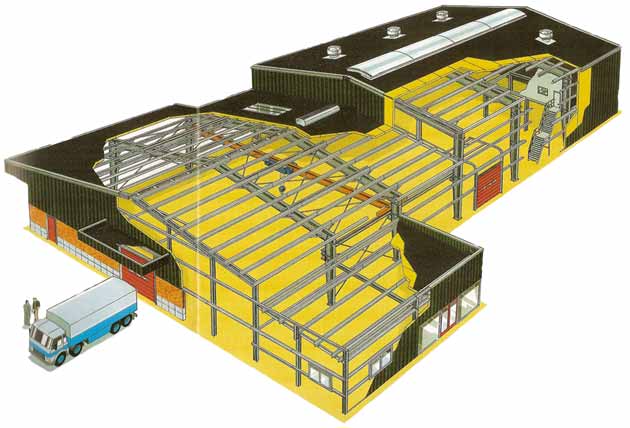
The structural schemes of one-story industrial buildings are diverse: the most common are single-span and multi-span frame schemes of frames with a coating system (flat and spatial) in the form of domes and cable-stayed structures. Coatings are made flat or pitched, with lanternless or lantern superstructures. One-story multi-span frame buildings come with spans of the same or different widths and heights or single-span. A span is an internal volume bounded by two rows of columns and end walls.
According to the type of construction materials, the frames are reinforced concrete and steel. Reinforced concrete frames can be monolithic and from standard prefabricated prefabricated reinforced concrete elements.
|
|
 |
|
 |
|
|
Structural scheme of the frame of a one-story industrial building: a - steel; b - reinforced concrete; in - wooden; 1- columns; 2- farms; 3- crane beams; 4 runs on farms; 5-horizontal links on farms; 6- vertical links between farms; 7- lantern frames; 8-horizontal lantern connections; 9- lantern runs; 10- vertical connections of the lantern; 11 - vertical connections along the columns; 12-reinforced concrete construction of the lantern; 13- single-branch column; 14 - two-branch column; 15 - coating plate; 16-walls; 17-foundation; 18- wooden glued beam; 19 - overhead crane; 20 - two-branch metal-wooden column; 21- wooden glued column |
|
The frame of a one-story building with a coating of flat elements consists of transverse frames formed by columns fixed in the foundations and trusses or beams hinged on the columns.
Frames are installed at a distance of 6 or 12 m from each other. Longitudinal elements of the frame rest on the frames: crane beams, along which paths are laid for overhead cranes, a crossbar of a wall frame (half-timbered), used to fasten window sashes and wall enclosing panels in case of their vertical cutting; reinforced concrete roof panels or steel roof purlins, on which profiled steel sheets or panels of asbestos-cement sheets and other materials; lanterns, the purpose of which is to provide natural aeration and lighting of buildings.
In the longitudinal direction, the frames are connected by crane beams, bracing beams, truss trusses, a rigid cover disk and, if necessary, steel ties. The hard disk is formed by plates welded to roof trusses or to beams, followed by monolithic seams. Flat structures cover spans up to 36 m.
Reinforced concrete wall panels are attached directly to the frame columns; lightweight metal or asbestos-cement panels are attached to steel crossbars or other elements of the wall frame attached to the columns.
In connection with the mass production of unified 6th wall and window panels, the 6th step is more often taken in the outer rows of columns. In order to efficiently and maneuverably use production space in the middle rows of columns, the 12th step is most common.
The spans of one-story industrial buildings are taken equal to 12, 18, 24, 30 and 36 m for workshops with crane loads and from 12 to 48 m or more for craneless workshops.
Prefabricated reinforced concrete columns can be solid rectangular section and two-branch.
 |
 |
 |
|
|
Schemes of frames of one-story industrial buildings a - with a flat roof; b - with a pitched roof and lanterns; 1 - fundamental beams; 2 - foundations; Z - columns of the extreme row; 4 - columns of the middle row; 5 - crane beams; 6 - roof beams; 7 - cover panels; 8 - drain funnel; 9 - insulation and roofing; 10 - parapet; 11 - wall panels; 12 - window bindings; 13 - floor; 14 - lantern; 15 - roof trusses |
|
One-story industrial buildings can have simple and complex shapes in plan.
At present, the rectangular shape with large dimensions of the building in plan (continuous building) is also predominant, eliminating the indicated disadvantages of separate building of the territory with small buildings.
Buildings of complex shapes: U-shaped, W-shaped and comb, similar to W-shaped, are used only for aerated shops with large heat and gas emissions (rolling, pressing, forging and similar shops), since a developed perimeter allows you to organize the inflow and air removal. To ensure ventilation of dead-end courtyards, their width must be at least half the sum of the heights of opposing buildings, but not less than 15 m (in the absence of harmful emissions, this value can be reduced to 12 m). Dead-end yards are located parallel or at an angle of 0-45 ° to the prevailing wind direction. The open side of the yard is turned to the windward side, and if, according to the planning conditions, such an arrangement is impossible, aeration openings at least 4 m wide and 4.5 m high are arranged in the closed side.
Depending on the characteristics of the technological process, one-story industrial buildings according to the space-planning solution can be span, hall, cell and combined type.
Span type buildings are used in cases where technological processes are directed along the span and are serviced by cranes. The span sizes of 12-36 m are chosen depending on the nature of the technological process, the dimensions of the equipment and products to be placed. The step of the internal vertical supports (columns) is usually 6 or 12 m, maybe more, but in all cases a multiple of 6 m.
Transport links between individual sections in span-type buildings are achieved with the help of overhead and overhead cranes, conveyors or floor transport.
Unified standard sections(UTS) and unified standard spans were used in the design of pavilion-type industrial buildings, both as continuous buildings and as separate buildings. By blocking typical sections and spans, it was possible to obtain various space-planning solutions for buildings.
A variety of dimensions of unified sections and spans made it possible to assemble from them industrial buildings of continuous development for various purposes and large area, which made it possible to place in them not only separate workshops of one enterprise, but also different industrial enterprises. TCBs were divided into crane and craneless.
For mechanical engineering enterprises, the dimensions of the main types of UTS are 72x72 and 144 × 72 m. For assembly and storage shops at mechanical engineering enterprises, there is a need to arrange longitudinal and transverse spans. In these cases, additional sections are used, the length of which is 72 m, and the width is 24, 30, 48 and 60 m with one or two spans.
Distinguish between longitudinal and transverse zoning. Zoning of production areas provides a more rational use of the volume of the building. It is advisable to locate workshops (departments) with large heat and gas emissions, fire and explosive processes near the outer walls of buildings, since ventilation and knock-out structures during an explosion are easier and more economical to solve. It is expedient to locate production facilities requiring air-conditioned conditions in the middle part of the building.
One-story industrial buildings span type may have a complex shape in plan. In individual design for one-story industrial buildings of a span type, the following dimensions of the grid of columns are often used:
- in craneless buildings without hanging equipment and with hanging handling equipment with a carrying capacity of up to 5 tons inclusive: 12X6, 18 × 6.24 × 6, 18 × 12, 24x12 m. A 12 × 6 m grid is used in small buildings;
- in buildings equipped with overhead cranes with a lifting capacity of up to 50 tons inclusive: 18X12, 24X12, 30X12 m. When designing, it should be borne in mind that an enlarged grid of columns allows more economical use of the production area. The grid of columns 18X12 or 24×12 m is optimal for most industries.
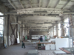
 The most commonly used industrial hangar type buildings. They are a set of standard modules that are blocked for a device of a specific production.
Most often, hangar-type buildings are used in the construction of: industrial workshops and buildings; warehouse complexes, hangars and terminals; covered markets and exhibition complexes; sports facilities; supermarkets and pavilions; car parks and service stations; shift camps; buildings and sheds for filling stations.
As a rule, one-story hangar-type buildings are used as single- and multi-span, without crane equipment and with cranes with a lifting capacity of up to 50 tons.
hangar building, as a rule, has a large span (reaching 100-150 m). The space-planning scheme of the building predetermines its constructive solution. So, U-shaped, L-shaped and through blocking schemes are accepted for spans up to 100 m with a transverse arrangement of supporting structures; with spans up to 150 m, a transverse-longitudinal arrangement of structures can be used, and with a linear one-sided or two-sided blocking scheme and a T-shaped one, cantilever load-bearing structures can be used.
When choosing a blocking scheme and solutions for supporting structures, further prospects for the development of aircraft construction, specialization and specifics of the expansion of the enterprise, as well as the conditions for typification, unification and economics are taken into account. The most flexible in terms of technology and economical - linear one-sided, L-shaped and through blocking schemes.
Hall type buildings- these are large-span one-story buildings without intermediate internal supports, they are used when the technological process is associated with the production of large-sized products or the installation of large-sized equipment: machine rooms of thermal power plants, hangars, aircraft assembly shops, main buildings of open-hearth and converter shops, etc. P.
Hall type buildings have recently become widespread in industries in which the technological process is not associated with the production of large-sized products or with the installation of large-sized equipment. This is due to the fact that the large size of production facilities allow free use of space, to accommodate any technological processes.
spans of buildings hall type may be 100 m or more. Such spans are usually covered with spatial structures. There are longitudinal and transverse arrangement of halls in the building. For aircraft assembly shops, a span of 60 m is quite appropriate, as it allows you to assemble aircraft with a wingspan greater than 60 m. In this case, the aircraft are placed on the conveyor at an angle to the longitudinal axis of the flight.
Hall-type buildings used for chemical industry enterprises with an enlarged grid of columns (24x12 or 30x12 m) make it possible to place multi-storey collapsible whatnots in them to accommodate process equipment. In such buildings, it is easy to upgrade equipment, change the technological process, introduce new technology without restructuring the main structures of the building.
Hall-type buildings with collapsible whatnots compared to multi-storey buildings have lighter floors, which reduces the mass of the building, and hence the cost of construction.
Frequent process upgrades are easier to implement in one-story buildings continuous building with a square grid of columns. Such a structure of a space-planning solution is called a cell structure, buildings are called flexible or universal. In cell type buildings, grids of columns 12 × 12, 18x18, 24 × 24, 30 × 30 and 36x36 m are most common.
The larger grid of columns makes it easy to change the placement of equipment and the direction of process flows. In flexible workshops, the height of all spans is assumed to be the same, and overhead cranes, conveyors or floor modes of transport are used as lifting and transport vehicles. In flexible workshops, significant changes in the technological process do not affect the structures of buildings, i.e. its space-planning and design solution remains constant. In addition, technological maneuverability of production, unification of space-planning and constructive solution, increasing the efficiency of the use of production areas, reducing the cost of construction.
Flexible Buildings received the greatest distribution in the machine-building industry (machine-tool building, tractor building, automobile building, etc.).
The useful area of flexible workshops is intended only for the placement of technological and transport equipment (conveyors, roller tables, etc.) of the main production process. Auxiliary premises that do not require a large height are placed on the mezzanine, in the inter-farm space or in outbuildings. Mezzanines are usually located near the outer walls of the building or on the border of workshops with different production modes or between enterprises blocked in one building. Mezzanines are arranged above utility rooms, intrashop passages and in the “dead” zone of crane equipment operation. The structural scheme of the mezzanines is most often framed with a grid of columns 6 × 6 m with collapsible structures.
Cell-type buildings are designed with natural and artificial lighting. To illuminate production areas in flexible workshops, so-called "floating" overhead lighting systems are used, the location of which does not depend on the size of the spans. The use of such systems allows you to obtain uniform illumination over the entire area of the workshop.
In buildings of the combined type, as the name implies, the space-planning solution can combine the features of buildings of span and hall types, span and cell types, etc.
